Characteristics of deep structure beneath Lhasa from multi-layer H-κ stacking method
-
摘要:
对不同深度莫霍面正演模拟的每条接收函数进行H-κ扫描,将得到的H和κ投影到平面图,发现同深度莫霍面的投影点能够拟合成一条曲线,进而通过该曲线能够分离不同深度界面对应的接收函数。在此基础上,再利用H-κ-θ方法计算估计倾斜界面的倾角和倾向。最终实现倾斜界面和“双莫霍”现象的辨识。利用此流程处理了拉萨固定台站(LSA)记录的大量接收函数,获得了拉萨台下方的地壳厚度约为70 km,地壳平均波速比约为1.67,莫霍面倾向北东,倾角为24°,而莫霍面下俯冲的印度板块界面深度约为106 km,倾向正北,倾角约为40°,其上方地幔楔内部的平均波速比约为1.69。正演模型计算结果和实际观测数据检验综合表明该方法能较好地区分不同界面对应的接收函数,藉此获取其界面的构造变化特征,有助于获得更加精细的壳幔结构特征。
Abstract:The Moho discontinuity, marking the boundary between the Earth’s crust and mantle, carries abundant information about the structure and evolution of the crust-mantle system. The “doublet Moho” phenomenon observed beneath the Tibetan Plateau complicates the investigation of Moho structure. The H-κ stacking of teleseismic receiver functions is a widely employed technique for determining Moho depth and crustal vP/vS ratios of horizontal layered crustal structure. The H-κ stacking was performed on each receiver function for different depth of the Moho from synthetic model. And, the obtained values of H and κ is projected onto a planar map, which reveals that the projected points corresponding to the same depth Moho interface align along a curve. Thus, the separated receiver functions is easily associated with distinct interface depths. Then, one can determine the dip direction of a tilted interface by analyzing the crustal thickness projection map. Subsequent processing can be targeted at each layer of receiver functions individually. Utilizing a large dataset of seismic recordings from LSA station of China Digital Seismograph Network, we follow the above-mentioned steps to separate the receiver functions of LSA and identify two key interfaces. Finally, employing the H-κ-θ method independently for each interface, we derived the following characteristics of the two interfaces: ① the crustal thickness beneath the Lhasa station is approximately 70 km with an average vP/vS ratio of about 1.67, and the Moho interface dips at an angle of 24°; ② the subducting Indian Plate interface lies at a depth of about 106 km with a dip angle of 40°. Above this interface of 106 km depth, the average vP/vS ratio within the mantle wedge between the two interfaces is approximately 1.69. Our results demonstrate the effectiveness of this method in distinguishing receiver functions corresponding to different interfaces. By integrating this approach with other techniques, more accurate subsurface structures can be elucidated, providing valuable insights into the geologic structure beneath the Qinghai-Xizang Plateau. This work contributes to a better understanding of the complex tectonic processes in this seismically active region.
-
Keywords:
- receiver function /
- multi-layer interface /
- dipping interface /
- LSA station
-
引言
莫霍面是地壳与地幔的分界面,莫霍面深度加上地表海拔即为地壳厚度,该厚度记录了地块本身的特殊构造演化过程。因此,对于不同的大地构造单元,其地壳厚度有明显的差异,如四川盆地和鄂尔多斯等大陆克拉通的地壳厚度约为40 km,青藏高原等正在造山的高原(许志琴等,2013)的地壳厚度大于60 km (He et al,2014),而正处于大规模伸展作用下的中国大陆东部的地壳厚度不到30 km (曾融生等,1995;高锐等,2009;He et al,2014;段永红等,2015)。大陆架地区的莫霍面变化趋势指示着大洋板块的新生和大陆板块的裂解(滕吉文等,2002;任建业等,2015),造山带地区的莫霍面几何结构反映了陆陆碰撞方式和大陆俯冲极性等方面的信息(Gao et al,2016;李玮等,2020)。因此,莫霍面变形特征,如产状信息(即倾角和倾向),更能揭示深部结构变形的动力学过程。
在探测莫霍面结构变化特征的各种地球物理方法中,利用莫霍界面上下显著的地震波速度差异(Kennett,1991)的主被动源地震探测尤为有效。例如,主动源深地震反射剖面探测(高锐等,2009)和被动源宽频带地震观测获得的远震接收函数记录(Langston,1977;Vinnik,1977;He et al,2014)是揭示莫霍面几何结构和地壳厚度的两种主要手段。与精度高、探测成本高和数据采集难度大的人工地震剖面方法(高锐等,2009)相比,利用将天然地震作为信号源的远震接收函数方法探测所得的莫霍面起伏变化成本低,且能满足莫霍面起伏变化的精度要求,因此该方法常用于探测较大区域的地壳厚度横向变化。远震接收函数的H-κ方法(Zhu,Kanamori,2000)可以快速地获取台站下方的地壳厚度和地壳平均波速比(泊松比),这对快速地认识台站下方的地壳物质组成,进而辨识地壳构造演化研究具有重要作用(Christensen,1996;嵇少丞等,2009)。
经典的H-κ扫描方法(Zhu,Kanamori,2000)是基于水平层状地壳模型,通过连续扫描给定范围的地壳厚度H和vP/vS波速比κ来判断最佳地壳厚度和波速比。若研究区域内界面发生倾斜,经典的H-κ扫描方法(Zhu,Kanamori,2000)得到的结果(H,κ)会产生较大偏差。为此,对应不同地壳结构特征发展出不同的H-κ扫描方法,主要从三个方面对其进行改进:输入数据挑选(Niu et al,2007)、计算过程控制(Li,Yuan,2003;张洪双等,2009;Wittlinger et al,2009;Yeck et al,2013;谭萍等,2018;Li et al,2019)、计算结果验证(Tian,Zhang,2013;Liu et al,2021)。改进后的H-κ扫描方法可以克服近地表沉积层厚度的影响(Yu et al,2015;危自根等,2016)、分离壳内震相(e.g.,Tang et al,2008)以及是否存在倾斜界面和壳内各向异性特征(e.g.,Lombardi et al,2008;房立华,吴建平,2009;查小惠等,2013;张洪双等,2013;Schulte-Pelkum,Mahan,2014;Xu et al,2017;Wang et al,2020,2022)等实际构造变形所导致的地壳结构变化产生的影响。整体而言,不论是经典的H-κ扫描方法(Zhu,Kanamori,2000),还是其改进方法(Lombardi et al,2008;房立华,吴建平,2009;查小惠等,2013;张洪双等,2013;Schulte-Pelkum,Mahan,2014;Xu et al,2017;Wang et al,2020;Wang et al,2022),均能获得波阻抗最大的莫霍面。但是在处理实际数据过程中,如果莫霍面附近存在其它界面,则会对扫描结果产生严重干扰,例如在青藏高原广泛存在的“双莫霍”现象(Kind et al,2002;Shi et al,2015,2016;Xu et al,2015)。
“双莫霍”现象是青藏高原南部莫霍面的一个典型特征,是指莫霍面附近有两个较强的Ps震相,难以区分哪个是真正的Ps震相。关于“双莫霍”现象中Ps震相走时滞后的界面,地学界对其认识比较统一,为拉萨地块的莫霍面;而对于Ps震相走时提前的界面则有不同的观点,有的认为是上地壳基底(Yuan et al,1997),或是主喜马拉雅逆冲断裂(main Himalayan thrust,缩写为MHT)界面(Mitra et al,2004),也有的认为是解耦的印度下地壳(Nábělek et al,2009;Wittlinger et al,2009)等。“双莫霍”现象的存在使得H-κ扫描结果具有多个接近最大值的极值对(H,κ),须由具有丰富经验的研究者从中选出合理的结果。显然,这将会导致地壳厚度H和地壳平均波速比κ的多解性。然而,众所周知,地壳内部结构具有唯一性。如果能分离两个界面的数据,则能减少“双莫霍”界面间信号的相互干扰,进而准确获取莫霍界面特征。
鉴于此,本文拟基于数值模拟和拉萨台多年记录到的接收函数数据,使用H-κ扫描方法区分同一个台站不同界面的优势信号,区分其对应的接收函数。如果存在倾斜界面,则判断其倾斜界面的倾向。之后,利用改进的H-κ扫描方法分别对每层界面的接收函数有针对性地定量计算,进而准确地求取每个界面的倾向和倾角。
1. 方法
1.1 H-κ扫描
单个台站下方的地壳厚度和波速比vP/vS可以通过H-κ扫描方法(Zhu,Kanamori,2000)获得。H-κ扫描方法的原理是使用一次Ps转换震相和后续多次转换震相PpPs和PpSs+PsPs获得合理的地壳厚度和vP/vS。地壳厚度H与波速vP和vS的关系如下:
$$ H=\dfrac{{t}_{{\mathrm{Ps}}}}{\sqrt{\dfrac{1}{{v}_{{\mathrm{S}}}^{2}}-{p}^{2}}-\sqrt{\dfrac{1}{{v}_{{\mathrm{P}}}^{2}}-{p}^{2}}}=\dfrac{{t}_{{\mathrm{PpPs}}}}{\sqrt{\dfrac{1}{{v}_{{\mathrm{S}}}^{2}}-{p}^{2}}+ \sqrt{\dfrac{1}{{v}_{{\mathrm{P}}}^{2}}-{p}^{2}}}=\dfrac{{t}_{{\mathrm{PpSs + PsPs}}}}{2\sqrt{\dfrac{1}{{v}_{{\mathrm{S}}}^{2}}-{p}^{2}}} \text{,} $$ (1) 式中:p为入射的射线参数,tPs为Ps转换震相与直达P波的到时间隔,tPpPs和tPpSs+PsPs分别为PpPs和PpSs+PsPs震相与直达P波的时间间隔。基于P波接收函数和初始S波速度,利用式(2)估算出地壳厚度H和波速比κ。
$$S ( H\text{,} \kappa ) =\frac{1}{N}\sum _{n=1}^{N}\left[{\omega }_{1}{A}_{n} ( {t}_{{\mathrm{Ps}}} ) + {\omega }_{2}{A}_{n} ( {t}_{{\mathrm{PsPs}}} ) -{\omega }_{3}{A}_{n} ( {t}_{{\mathrm{PpSs + PsPs}}} ) \right] \text{,} $$ (2) 式中,S为H-κ扫描结果,An (t)为第n条接收函数中t时刻的地震信号幅值,ω1, ω2和ω3分别为Ps,PpPs和PpSs+PsPs等三个相位在计算过程中的权重。
1.2 分方位H-κ扫描
如果界面发生倾斜,会导致H-κ扫描结果产生误差(Lombardi et al,2008; Schulte-Pelkum,Mahan,2014; Wang et al,2022)。为此,将每条接收函数的H-κ扫描结果按照穿透点位置进行还原,得到台站下方莫霍面的形态特征;然后,根据界面深度的梯度方向判断倾斜界面的倾向。接收函数的横向传播距离表示如下:
$$ \left\{\begin{array}{l} {D}_{{\mathrm{S}}}=\dfrac{H p {v}_{{\mathrm{S}}}}{\sqrt{1-{v}_{{\mathrm{S}}}^{2}{p}^{2}}}\text{,} \\ {D}_{{\mathrm{P}}}=\dfrac{H p {v}_{{\mathrm{P}}}}{\sqrt{1-{v}_{{\mathrm{P}}}^{2}{p}^{2}}}\text{,} \end{array}\right. $$ (3) 式中:DS和DP分别为S波和P波的横向传播距离,H为界面深度,p为射线参数。根据横向传播距离和后方位角,计算出深度H处的射线穿透点位置。对单条P波接收函数进行H-κ扫描后,对于每个扫描的深度H,依据式(3)计算出S波横向传播距离DS。最后,在扫描深度H处记录到穿透点位置。如果界面发生了倾斜,依据梯度计算公式
$$\nabla f ( x\text{,} y ) =\frac{ {\text{∂}} f}{ {\text{∂}} x}{{\boldsymbol{i}}} + \frac{ {\text{∂}} f}{ {\text{∂}} y}{{\boldsymbol{j}}}$$ (4) 求取最大梯度方向,进而获取其倾向。式中:x和y分别为穿透点的经度和纬度,f (x,y)代表点(x,y)处的梯度值,i和j分别表示x和y方向上的单位向量。
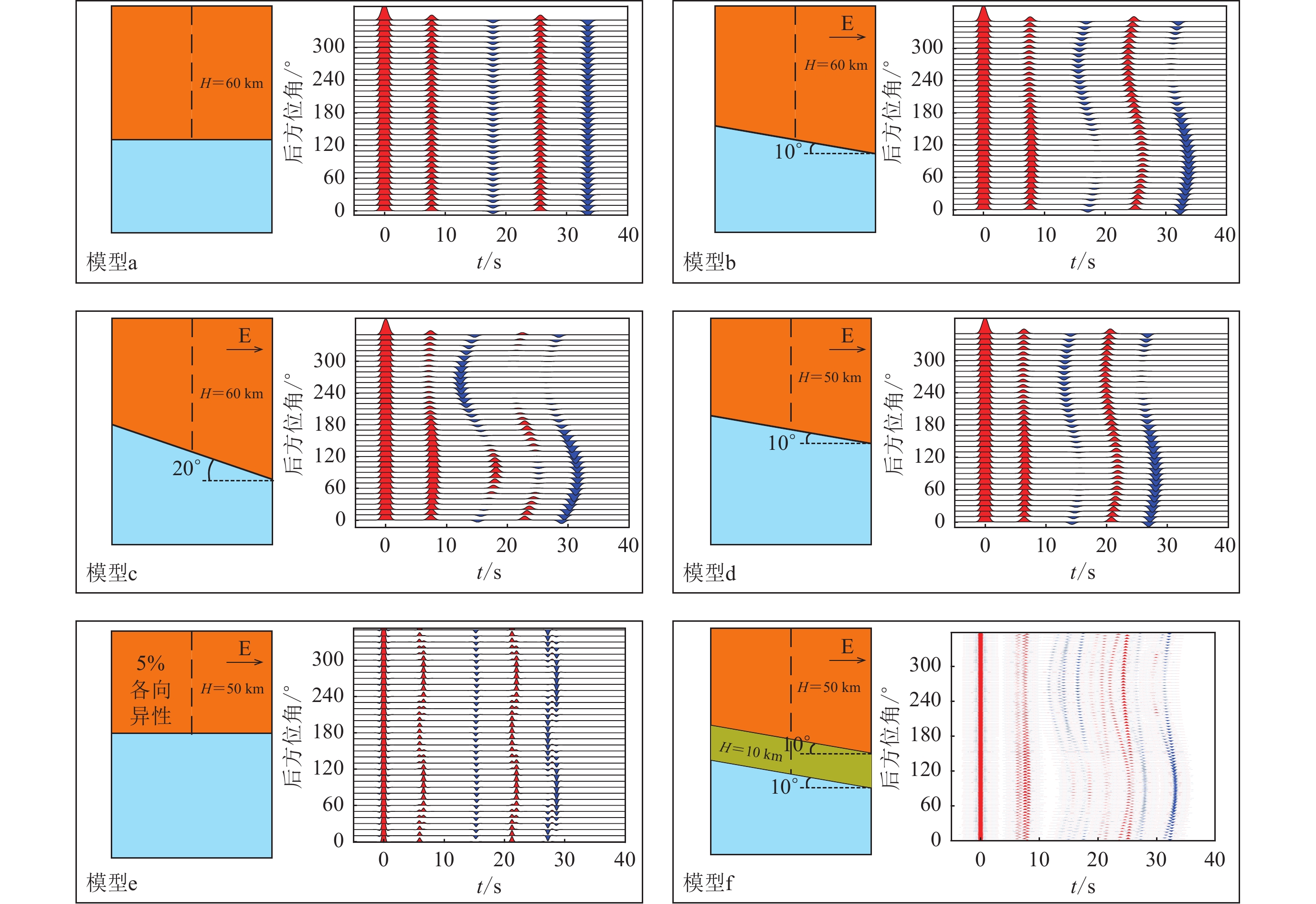
为验证该方法,我们利用RAYSUM软件 (Frederiksen,Bostock,2000)通过对理论模型(表1)进行正演模拟得到接收函数(图1)。
表 1 正演模型参数Table 1. Forward model parameters模型编号 界面深度/km 界面倾向 界面倾角/° 各向异性 震中距/° 模型层数 模型参数 vP/(km·s−1) vP/vS a 60 − − − 30,60,90 2 上层
下层6.2
8.11.77
1.77b 60 正东 10 − 30,60,90 2 c 60 正东 20 − 30,60,90 2 d 50 正东 10 − 30,60,90 2 e 50 − − 5% 60 2 f 50,60 正东 10 − 30,90 3 上层
中层
下层6.2
7.1
8.11.77
1.77
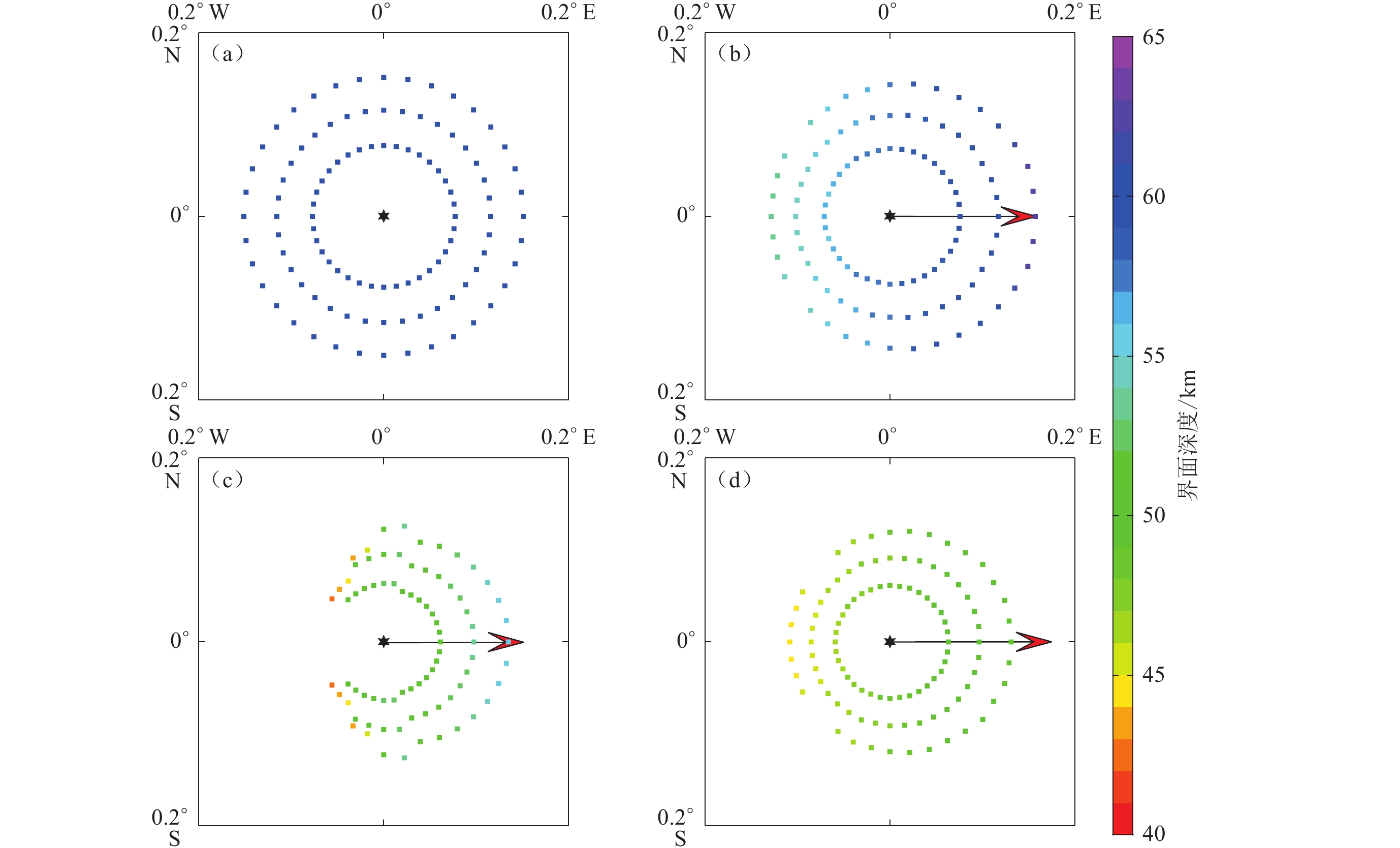
1.77采用分方位H-κ扫描方法对表1中的a,b,c和d这四个模型的接收函数进行计算,本文中计算结果H为界面深度,即地壳厚度减去台站高程。H-κ扫描参数设置H为40—65 km,步长为0.1 km;κ为1.7—2,步长为0.001;vP按照模型选为6.2 km/s;Ps,PpPs和PpSs+PsPs三个相位权重为0.5,0.3,0.2。扫描结果如图2所示。对于水平层状模型(图2a),其结果与传统H-κ扫描结果一致,表明对于水平界面,传统方法扫描结果准确;对于倾斜界面模型(图2b,c,d),其扫描结果产生误差,但界面倾斜的方向都准确。对比图2b与图2c可知,倾斜界面模型对H-κ扫描结果影响较大,角度越大,扫描深度越浅,特别是对于后方位角与界面倾向方向相反的接收函数,其H-κ扫描结果误差更大,当倾角达到20°时,正西方向的接收函数的扫描结果超出数据边界,因此舍去,在图2c中缺失。图2d中,界面深度为50 km,分方位H-κ扫描的数据完整性与图2b相近,扫描界面深度结果与图2c相近,表明倾斜界面通常会造成所获界面深度偏浅。
![]() 图 2 正演模型(表1中所列)的分方位H-κ扫描结果图中红色箭头为最大梯度方向,红色箭头长度为归一化后的梯度大小。(a) 模型界面水平,界面深度H为60 km;(b) 模型界面倾角θ为10°,H为60 km;(c) 模型界面θ为20°,H为60 km;(d) 模型界面θ为10°,H为50 kmFigure 2. The H-κ stacking result in azimuth for the four forward models listed in Table 1The red arrow points to maximum gradient,the length of the red arrow represents the size of the normalized gradient. (a) Horizontally interface and interface depth 60 km;(b) Interface with inclination 10° and depth 60 km;(c) Interface with inclination 20° and depth 60 km;(d) Interface with inclination 10° and depth 50 km
图 2 正演模型(表1中所列)的分方位H-κ扫描结果图中红色箭头为最大梯度方向,红色箭头长度为归一化后的梯度大小。(a) 模型界面水平,界面深度H为60 km;(b) 模型界面倾角θ为10°,H为60 km;(c) 模型界面θ为20°,H为60 km;(d) 模型界面θ为10°,H为50 kmFigure 2. The H-κ stacking result in azimuth for the four forward models listed in Table 1The red arrow points to maximum gradient,the length of the red arrow represents the size of the normalized gradient. (a) Horizontally interface and interface depth 60 km;(b) Interface with inclination 10° and depth 60 km;(c) Interface with inclination 20° and depth 60 km;(d) Interface with inclination 10° and depth 50 km1.3 单台H-κ平面图
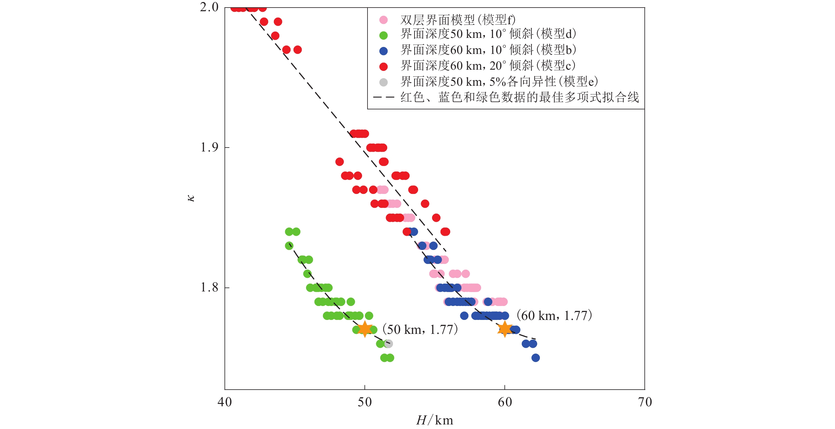
将每条接收函数的H-κ扫描结果投影至H-κ平面图(图3),该图清楚地展示了各向异性模型分方位扫描结果(灰色圆点)比较靠近50 km深度,这表明分方位H-κ扫描方法不适用于各向异性结构(图1中模型e)。而双层界面模型(图1中模型f)扫描结果(图3粉色圆点)集中于60 km深度处异常,与蓝色圆点比较接近。图3中两个橙色六角星分别代表如图1所示的界面深度为50 km和60 km的模型,两个模型的κ值均为1.77。如图3所示,将同一深度且不同倾角界面的分方位H-κ扫描结果投影在H-κ平面可拟合为一条曲线,而不同界面深度的分方位H-κ扫描果在H-κ平面图中分别能拟合到不同曲线上。众所周知,H-κ扫描方法通常得到的是壳幔内部最强波阻抗界面(莫霍面)的深度和波速比(Zhu,Kanamori,2000)。若莫霍面附近有其它强波阻抗界面,就会对扫描结果产生强干扰。因此,对于双层模型的模拟数据,由于60 km界面的波阻抗较大,扫描结果均集中在60 km界面附近。但是在实际观测数据的处理过程中,由于远震事件的震中距不同等原因,可以通过分方位H-κ扫描得到对应界面的拟合曲线。在接收函数方法中,不同界面产生的震相及后续多次波是互相独立的,如果能够区分不同界面产生的信号及多次波,再使用H-κ扫描便可提高界面的分辨率,进一步得到界面的构造信息。依据正演模型数据(图1),将每一条接收函数的H-κ扫描结果投影至H-κ平面,之后进行线性拟合(图3)。依据能否拟合到一条线上,将不同深度的界面产生的接收函数进行区分,即可区分不同深度界面产生的转换波和多次波,之后分别对不同深度的接收函数进行H-κ扫描,得到更准确的界面倾向和倾角信息。
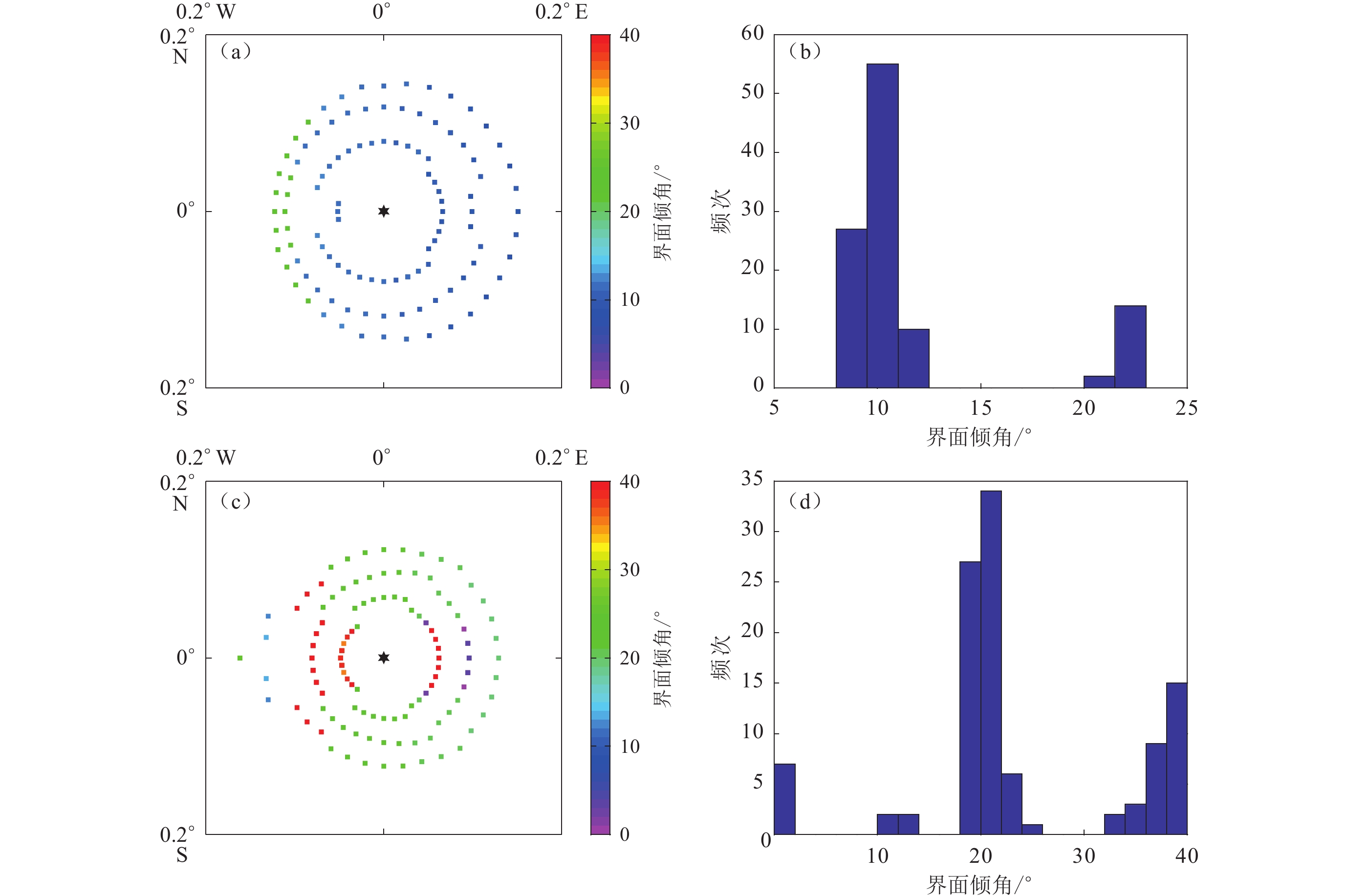
通过对正演模型(图1)执行分方位H-κ扫描和单台H-κ平面图分析,确定倾斜界面的倾向为正东方向(图2)。若要进一步获得界面倾角信息,本研究采用适用于倾斜界面的H-κ-θ扫描方法(谭萍等,2018;Li et al,2019;Wang et al,2020)。该方法计算公式增加了界面倾向、界面倾角和下界面P波速度等三个参数。确定三个参数中的任意两个,扫描即可得到第三个参数。通过分方位H-κ扫描得到模型界面倾向为正东方向,而莫霍界面以下的速度采用vP为8.1 km/s,对倾角进行扫描。图4a和c展示了由分方向H-κ-θ扫描得到的倾角,可见:大部分扫描结果能得到准确的倾角,相对应的H和κ值与正演模型一致;也与分方位H-κ扫描结果类似,正西及附近方向的扫描结果误差大,倾角越大,误差也越大,而南北方向的扫描误差小。直方图(图4b,d)结果显示H-κ-θ扫描对不同倾角扫描的优势结果与倾角大小一致,倾角越小,计算结果越集中。
两个模型数据全部叠加的H-κ-θ扫描结果见图5,将扫描结果最大值以二阶泰勒展开来估计其误差(Zhu,Kanamori,2000)。图5a展示了倾角为10°的莫霍面模型扫描结果,即H=(60.4±0.24) km,κ=1.776±0.05,倾角为10°。图5b则展示了倾角为20°的模型扫描结果,H=(60.9±0.25) km,κ=1.785±0.06,倾角为22°。利用分方位H-κ-θ的扫描结果(图5)与初始模型(图1b,c)比较接近,尽管随着倾角的增大,叠加的能量较为分散,但整体上能够得到模型的界面倾角及H值和κ值。
2. LSA台站数据检验
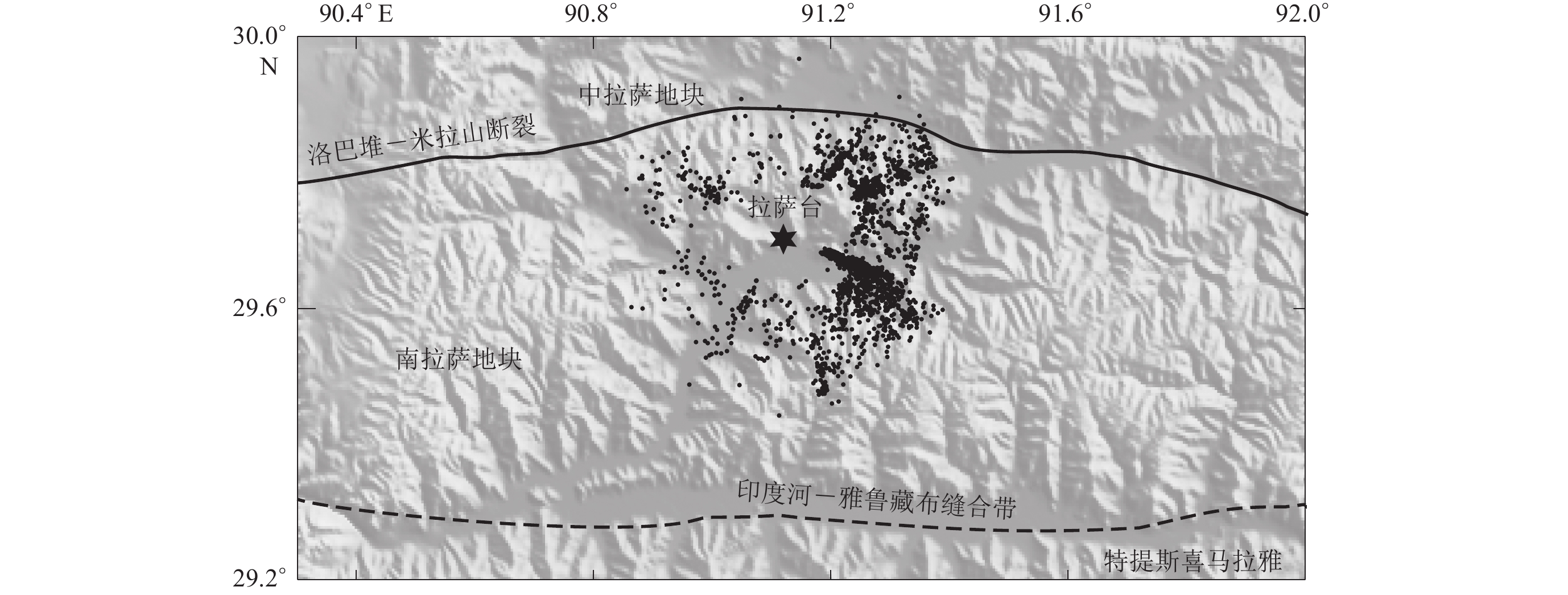
拉萨地块位于青藏高原南部,属碰撞前缘构造带,其下的壳幔结构复杂(He et al, 2010)。而如图6所示的位于碰撞前缘的拉萨永久观测台站(LSA)下方的莫霍面转换震相较复杂(Yuan et al,1997;Kind et al,2002),且下层界面北东向倾斜30° (Li et al,2011),因此基于上述正演方法,我们选择了拉萨台站,试图获取其下方的“双莫霍” (Li et al,2011)的双界面倾向和倾角。为此,我们收集了2008年至2021年期间拉萨台站记录的远震地震事件波形数据。
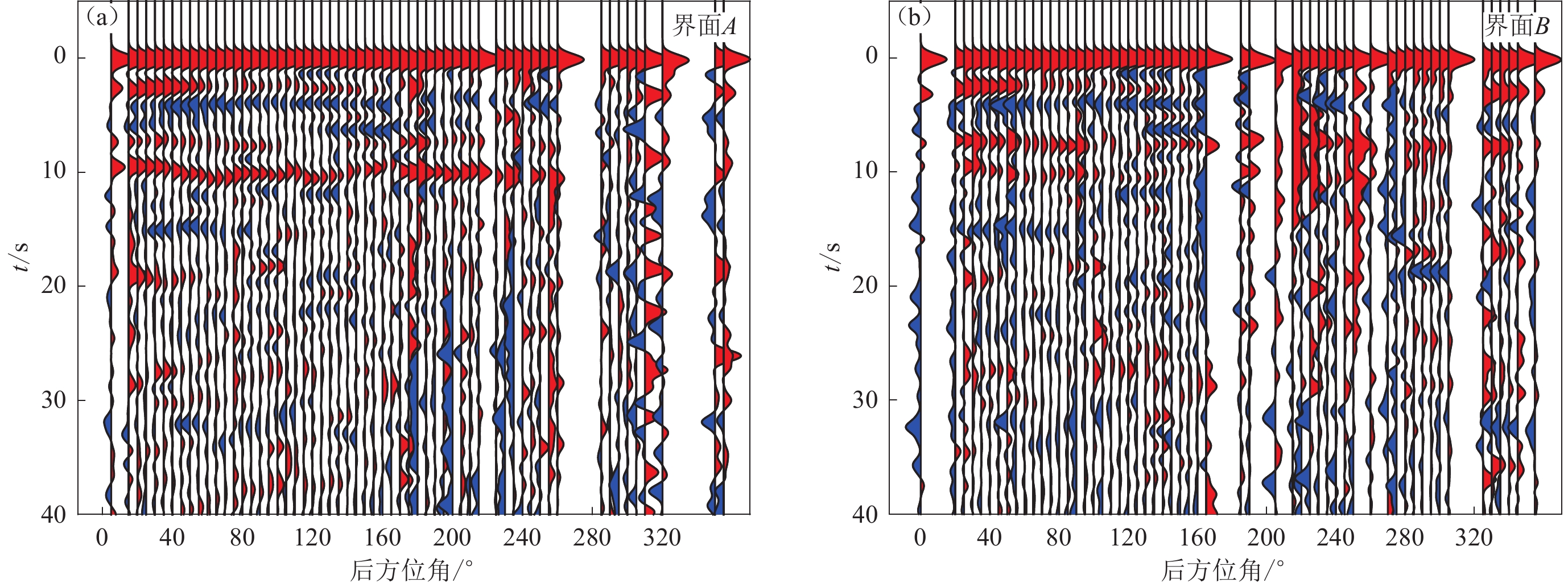
首先,接收函数提取。在美国地质调查局网站的地震目录中选取MS>6.0、震中距介于30°—90°之间的地震事件,截取P波初至前20 s到后100 s的三分量数据,数据采样频率取10 Hz;去均值、去线性趋势和尖灭后,使用频率范围0.05—5 Hz进行带通滤波;将三分量地震数据从Z-N-E (垂向、北向和东向)旋转到Z-R-T (垂向、径向和切向)坐标系;采用时间域迭代反褶积方法(Kind et al,1995;Ligorría,Ammon,1999)计算P波接收函数,其中高斯系数选取1.5;使用Crazyseismic软件包(Yu et al,2017)对接收函数进行挑选,获取高信噪比的接收函数。经过人工挑选,共得到2 619条高质量的接收函数。如图6中黑色圆点所示的接收函数在80 km深度的穿透点位置显示接收函数分布较为均匀,符合开展本方法方位分布均匀的要求。将所有接收函数按后方位角5°分区并叠加排列(图7a),可见10 s和7 s附近存在两个强转换震相,10 s震相较为连续并仅在后方位角300°附近减弱,而7 s震相在后方位角120°和300°附近减弱。
![]() 图 7 拉萨台站P波接收函数和H-κ平面图(a) 拉萨台站全部接收函数按方位角5°范围叠加排列;(b) 拉萨台站分方位扫描后的H-κ平面图Figure 7. P-wave receiver functions beneath LSA station and their H-κ stacking image(a) All of stacked receiving functions of LSA stations arranged in 5° azimuth bin;(b) The H-κ plan diagram of the LSA station after stacking in azimuth
图 7 拉萨台站P波接收函数和H-κ平面图(a) 拉萨台站全部接收函数按方位角5°范围叠加排列;(b) 拉萨台站分方位扫描后的H-κ平面图Figure 7. P-wave receiver functions beneath LSA station and their H-κ stacking image(a) All of stacked receiving functions of LSA stations arranged in 5° azimuth bin;(b) The H-κ plan diagram of the LSA station after stacking in azimuth其次,分方位扫描和倾斜界面分析。采用分方位H-κ扫描方法计算,扫描参数设置H为50—100 km,步长为0.1 km;κ为1.5—2.0,步长为0.01;P波波速根据拉萨地块内折射测量的速度结构(Wang et al,2021)选取6.2 km/s;Ps,PpPs和PpSs+PsPs等三个相位的权重分别为0.5,0.3和0.2。根据扫描结果得到拉萨台站的H-κ平面图,如图7b所示,显然H-κ值分布可拟合为两条曲线,分别用红色圆点和蓝色圆点标记。根据正演模型的分析,可推断台站下方存在两层倾斜界面。将红点、蓝点所代表的界面分别记作界面A和B,并舍去黑点所示的不属于两个界面的信号。
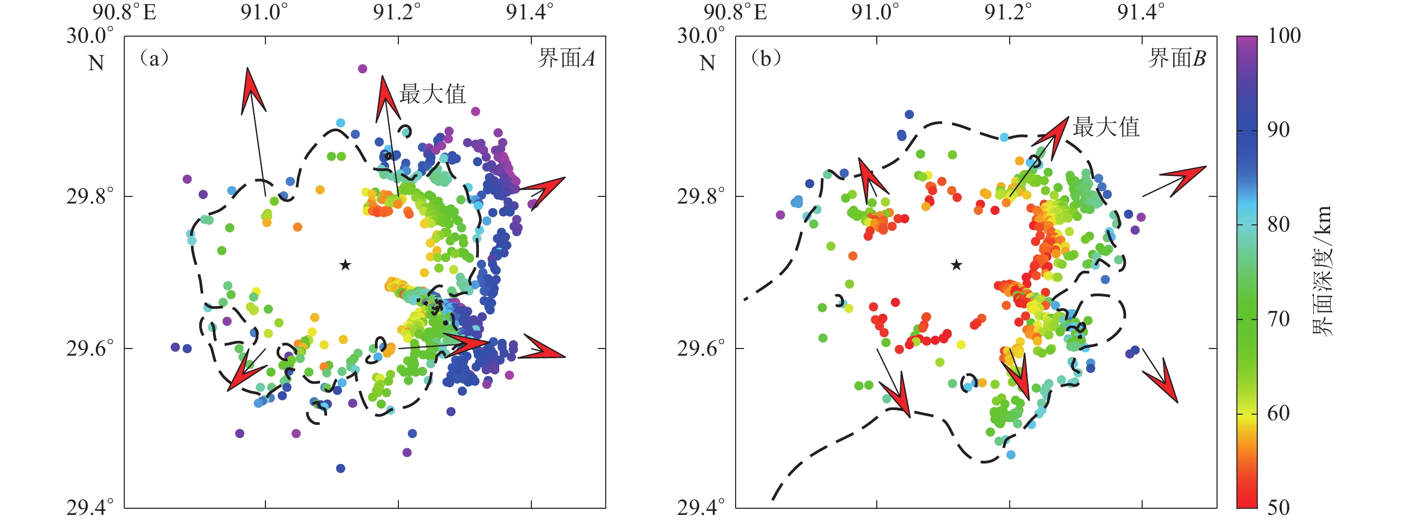
再次,依据图7所示的特征,分离界面A和B对应的接收函数,其中界面A和B分别有
1178 条(图8a)和656条接收函数(图8b),且两界面提取到的接收函数占全部接收函数的70%。对两界面接收函数采用分方位H-κ扫描获取各自的倾向特征,结果如图9所示。与模拟数据的梯度结果(图2)不同,实际数据计算的梯度有多个方向,梯度大小也各不相同,因此,根据选取梯度最大方向作为可能的界面倾向并结合区域内相关研究成果予以判断。深地震反射剖面探测(Gao et al,2016)和接收函数分析(Li et al,2009)都显示出拉萨台站下方莫霍面变化趋势自南向北逐渐加深(Li et al,2009;Chen et al,2010),且其下方界面倾向北东(Li et al,2011)。考虑到印度板块持续北向俯冲(He et al,2010;许志琴等,2013)以及由H-κ-θ扫描获取的倾向误差小于30°且在误差范围内(谭萍等,2018),将界面A的倾向确定为正北方向(图9a),界面B的倾向确定为北东方向(图9b)。![]() 图 9 拉萨台站下方界面A (a)和B (b)的分方位H-κ扫描投影图图中红色箭头的方向和长度代表梯度的方向和大小,黑色虚线代表80 km等深线Figure 9. The projected map of H-κ scanning in azimuth results of interfaces A (a) and B (b) beneath LSA stationThe direction and length of the red arrow represents the direction and size of the gradient,the black dashed line represents the 80 km iso-depth contour line
图 9 拉萨台站下方界面A (a)和B (b)的分方位H-κ扫描投影图图中红色箭头的方向和长度代表梯度的方向和大小,黑色虚线代表80 km等深线Figure 9. The projected map of H-κ scanning in azimuth results of interfaces A (a) and B (b) beneath LSA stationThe direction and length of the red arrow represents the direction and size of the gradient,the black dashed line represents the 80 km iso-depth contour line最后,利用H-κ-θ扫描获取界面A和B的倾向信息。界面A的计算参数取值如下:H范围为60—120 km,步长为0.1 km,κ范围为1.5—2.0,步长为0.001,界面上层vP为6.5 km/s,界面下层vP为8.1 km/s;界面B的计算参数取值如下:H范围为40—80 km,步长为0.1 km,界面上层vP为6.2 km/s,界面下层vP为7.1 km/s,κ值及步长与界面A相同。H-κ-θ扫描计算结果如图10所示。
如图10a所示,界面A的深度为(106.6±0.13) km,其倾角为40°,而界面A以上壳幔结构的vP/vS (κ值)为1.691±0.04。图10b所展示界面B的深度为(66.7±0.10) km,倾角为24°,而其上方的地壳vP/vS (κ值)为1.669±0.04。而图10c所展示的传统H-κ扫描结果指示其vP/vS最大值靠近其边界,根据前人结果(Li et al,2011;He et al,2014)将H和κ分别修正为76.4 km和1.75,此深度与图10b所示的界面B的深度接近,而与界面A的深度(图10a)相差约30 km。正演模型结果(图10)以及前人对倾斜界面的H-κ扫描结果(房立华,吴建平,2009;查小惠等,2013;谭萍等,2018)表明倾斜界面的扫描结果比真实值偏小,而在界面倾斜的情况下,真实深度比水平界面扫描深度深。对于倾斜界面的倾向和倾角,Li等(2011)对拉萨台站P波和S波接收函数的综合分析认为,拉萨台站下方60 km深度界面水平,而约80 km深度的下层界面倾向北东,倾角为30°。而分方位H-κ-θ结果(图10a,b)显示北东倾向的上层界面B倾角较小,约为24°,而正北倾向的下层界面A的倾角较大,约为40°,其中,界面A的形态(图10a)与Li等(2011)界面形态大致相符,但深度更深,约为106 km。一般情况下,接收函数中形成的Ps转换波在10 s附近的界面深度在80 km附近,而如图8a所示的10 s的Ps震相的界面深度在106 km (图10a)。 这缘于以下两个原因:其一是H-κ扫描结果中的波速比(1.69)较平均地壳波速比(1.73)偏小,造成波速vP与vS之差减小,因此在时间间隔相同的情况下,界面深度更深;其二,与水平界面相比,倾斜界面形成的Ps震相走时缩短。在两因素的共同作用下,拉萨台站下方两个Ps震相的H-κ扫描深度相较传统结果偏深。为了进一步确认界面A和界面B的结果可靠性,依据两个界面深度和界面上方波速比估算此两层界面间的波速比,表达式为:
$$ \left\{\begin{array}{c} \dfrac{h_2}{v_{\mathrm{P}2}}=\dfrac{h_2-h_1}{v_{\mathrm{P}\mathrm{m}}}+\dfrac{h_1}{v_{\mathrm{P}1}} \text{,} \\ \dfrac{h_2}{v_{\mathrm{S}2}}=\dfrac{h_2-h_1}{v_{\mathrm{S}\mathrm{m}}}+\dfrac{h_1}{v_{\mathrm{S}1}}\text{,} \end{array}\right. $$ (5) 两层界面之间波速比κ为:
$$ \kappa =\dfrac{{h}_{2}{\kappa }_{2}-{h}_{1}{\kappa }_{1}\dfrac{{v}_{{\mathrm{P}}2}}{{v}_{{\mathrm{P}}1}}}{{h}_{2}-{h}_{1}\dfrac{{v}_{{\mathrm{P}}2}}{{v}_{{\mathrm{P}}1}}}\text{,} $$ (6) 式中:上下层界面的深度分别为h1和h2,上下层界面地层的平均波速比分别为κ1和κ2,上下层界面的P波平均速度分别为vP1和vP2,上下层界面的S波平均速度分别为vS1和vS2;界面间P波和S波的平均速度分别为vPm和vSm;两层界面之间的波速比为κ。
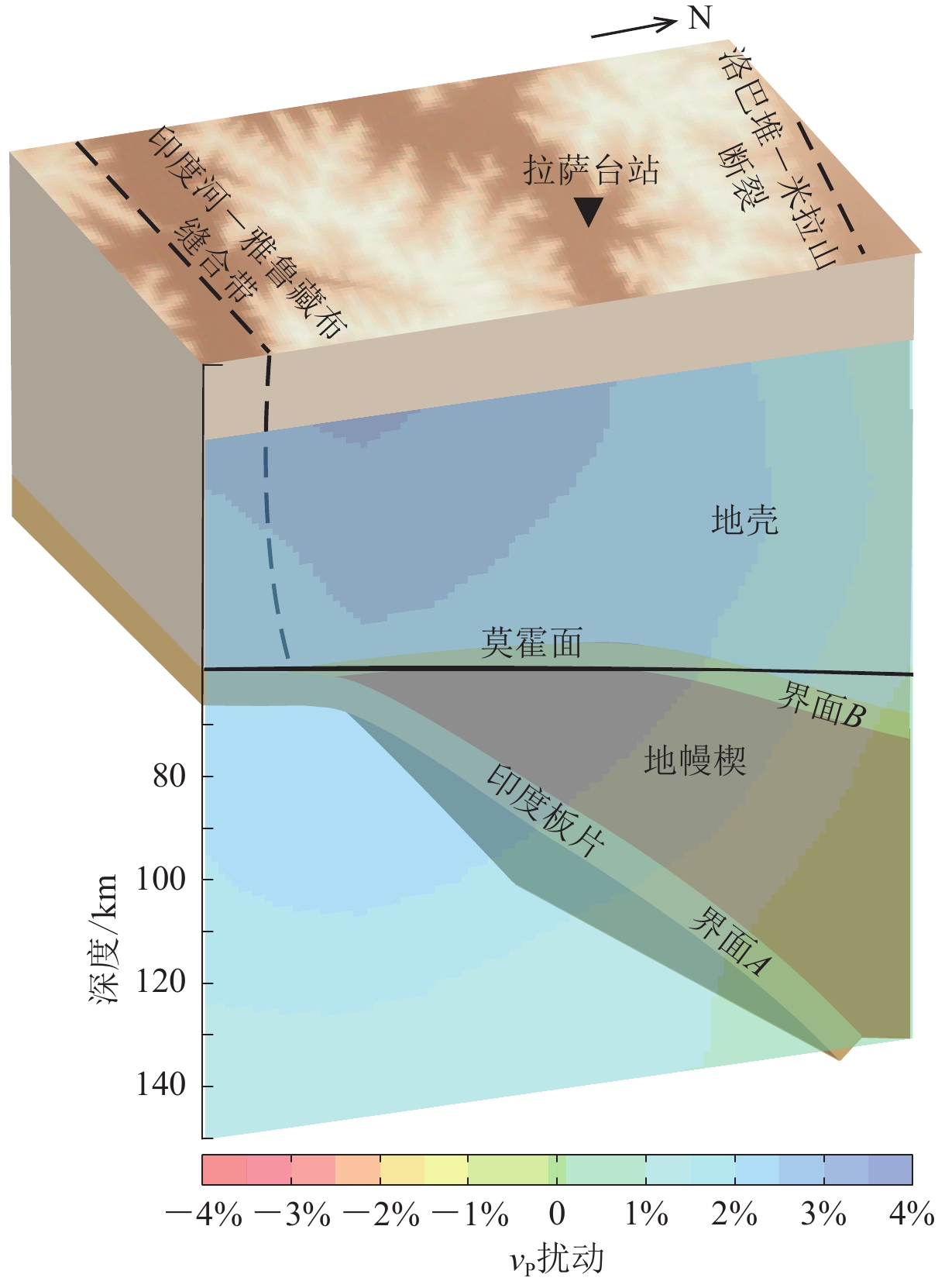
利用本文方法获取了拉萨台站下存在倾斜界面A $ [ $深度为(106.6±0.13)km,κ=1.691±0.04,倾角为40°$ ] $和界面B $ [ $深度为(66.7±0.10) km,κ=1.669±0.04,倾角为24°$ ] $这两个关键结构特征,而这两个界面间的κ值约为1.73,揭示了如图11所示的陆陆碰撞俯冲前缘下的地幔楔状结构特征(He et al, 2010)。
![]() 图 11 拉萨台站下方界面模型与层析成像结果对比(引自He et al,2010)Figure 11. Comparison of subsurface interface model beneath the LSA station with tomographic imaging results (after He et al,2010)
图 11 拉萨台站下方界面模型与层析成像结果对比(引自He et al,2010)Figure 11. Comparison of subsurface interface model beneath the LSA station with tomographic imaging results (after He et al,2010)3. 讨论
拉萨台站位于南拉萨地块,处于印度板块与欧亚大陆碰撞的前缘,其下的壳幔结构较为复杂。已有的接收函数分析已清楚地显示了其下方的莫霍面附近有两个界面,分别位于60 km和80 km处,且下界面为30°的北倾界面(Yuan et al,1997;Kind et al,2002;Li et al,2011)。研究区域内的深地震反射剖面探测结果(Gao et al,2016)显示南拉萨地块的莫霍面深约70 km,且印度板块已俯冲至其下(Zhao et al,1993;Dong et al,2020)。该地区的三维电阻率结构(Jin et al,2022)显示70 km深度存在一个低阻与高阻的分界面,且印度板块俯冲至拉萨板块之下(Wei et al,2001)。根据He同位素的地球化学填图(Klemperer et al,2022;Zhao et al,2022),在拉萨台站下方存在幔源He同位素。界面A的深度为106 km (从地表算起为110 km)和界面B的深度为66 km (从地表算起为70 km,即地壳厚度)。下面将重点讨论拉萨台站下方存在的两个倾斜界面(界面A和界面B)的关键构造属性。
1) 界面A为北向俯冲的印度岩石圈地幔的顶界面。界面A由于倾角较大,深度更深,结合区域研究结果(Li et al,2008;Priestley et al,2008;He et al,2010;Zhao et al,2010;Xiao et al,2020),推测其为俯冲至拉萨地块之下的印度岩石圈地幔顶部(图11)。根据藏南区域He同位素研究结果(Klemperer et al,2022;Zhao et al,2022),印度板块在拉萨台站南部区域与青藏高原地壳分离,造成幔源He含量增加。因此,如图8所示的拉萨台站7 s和10 s的信号分别代表了台站下方的莫霍面(界面B)和俯冲的印度板块(界面A),二者之间形成地幔楔结构(图11)。
2) 界面B为莫霍面。界面B的深度(地壳厚度为70 km)与其它研究对拉萨台站地壳厚度计算结果接近(高星等,2005;Chen et al,2010;Shen,Zhou,2012;He et al,2014;Link et al,2020)。北东倾向的界面B倾角约为24°,结合图9b中的梯度大小和方向,界面B的局部起伏较大。结合区域内深地震反射探测的70 km地壳厚度(Gao et al,2016;Guo et al,2018;Dong et al,2020;Lu et al,2022),将界面B定义为莫霍面,如图11所示。
3) 界面A与界面B组成的地幔楔构造特征。以35 km的地壳厚度为基准,早期的Herrin模型(Herrin,1968)和
1066 模型(Gilbert,Dziewonski,1975)的地幔波速比约为1.7。初步参考地球模型(Preliminary Reference Earth Model,简写为PREM)(Dziewonski,Anderson,1981)、PWDK模型(Weber,Davis,1990)、IASP91模型(Kennett,Engdahl,1991)、SP6模型(Morelli,Dziewonski,1993)和AK135-f模型(Kennett et al,1995)在地幔处的波速比约为1.79。对比上述数值,本次研究得到的由界面A与界面B组成的地幔楔内部物质的波速比约为1.73也较合理。青藏高原从中生代以来分别经历了新特提斯洋俯冲和印度板块碰撞。地幔楔常存于洋陆俯冲,洋壳物质在俯冲过程中发生蛇纹石化,造成波速比升高(Ji et al,2013;申婷婷等,2016)。陆陆碰撞造成区域内地壳厚度(约70 km)是正常地壳厚度的两倍,在洋陆俯冲时期形成的蛇纹石在高温高压条件下脱水,重新形成橄榄岩。因此,研究区域(图6)先后经历洋壳俯冲和陆陆碰撞与俯冲的持续改造,显然不同于仅由洋壳俯冲所形成的地幔楔。
青藏高原的巨厚地壳导致70 km之下的地幔楔内具有较高的温压,且含水量更少,这使得波速比降低。在位于拉萨台站以南的雅鲁藏布江缝合带内,蛇绿岩出露并不明显(常承法,1980;Nicolas et al,1981;王成善等,2005;张万平等,2011),但带内分布大量蛇绿岩(Girardeau et al,1985),所以有可能大部分蛇绿岩仍滞留在下地壳或地幔中。在藏南下地壳或地幔的温压条件下(Priestley et al,2008),蛇绿岩中大部分矿物发生脱水反应,最终稳定存在的是橄榄岩类矿物(申婷婷等,2016)。橄榄石的波速比约为1.73 (Christensen,1996),或约为1.75 (Christensen,Ramananantoandro,1971)。所以,界面A与B之间的波速比(1.73)也符合实际(Christensen,Ramananantoandro,1971; Christensen,1996;申婷婷等,2016)。而莫霍面(界面B)之上的平均波速比仅为1.67,表明地壳中二氧化硅含量较高(Wang et al,2021),符合青藏高原长英质岩浆注入所导致的地壳增厚学说(侯增谦等,2020;Wang et al,2021)。
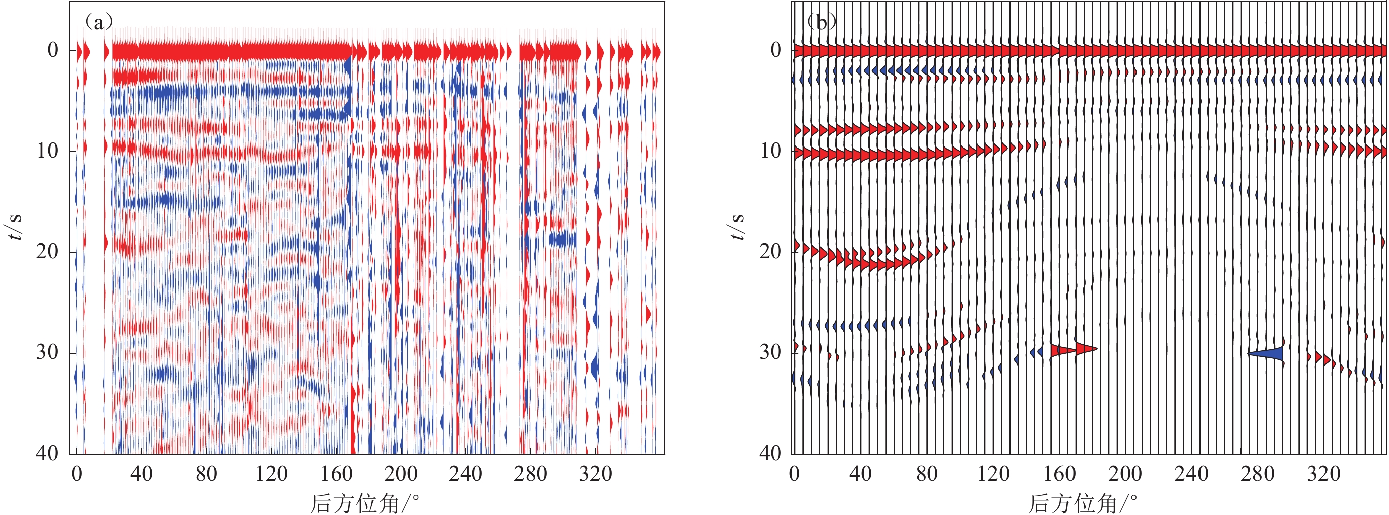
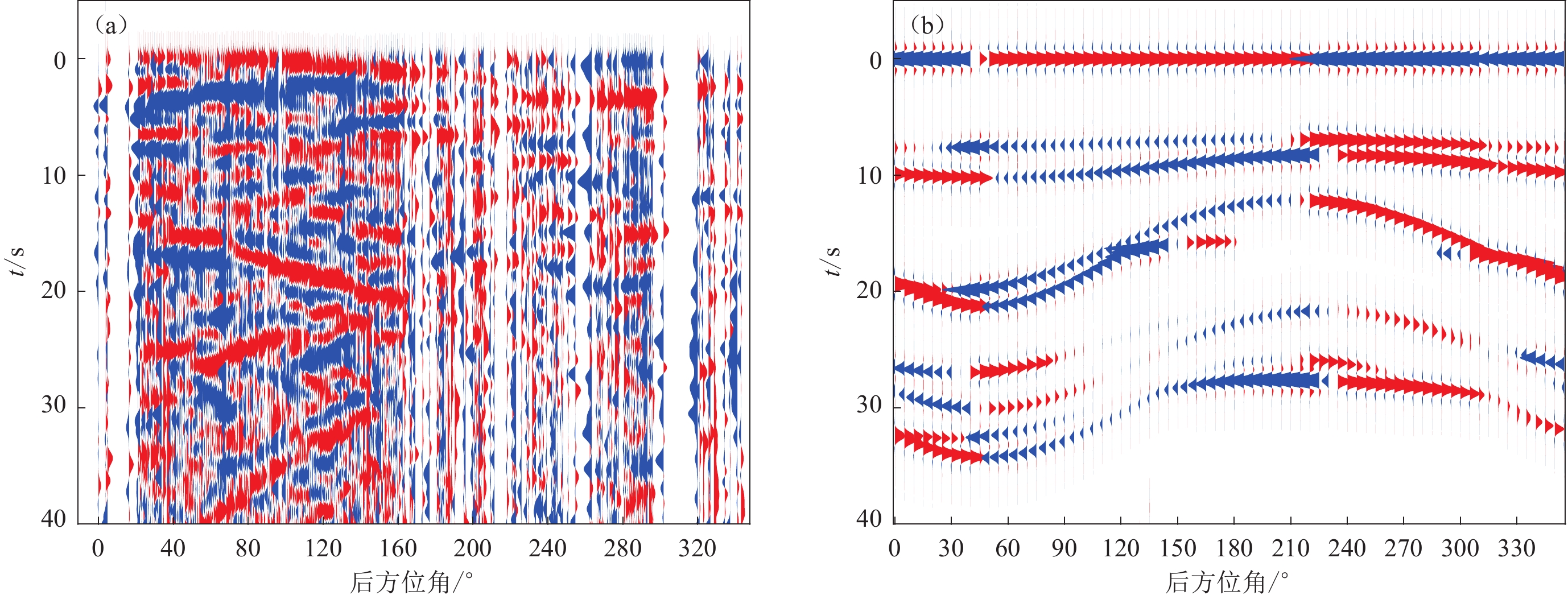
4) 南拉萨地块下的壳内各向异性特征。南拉萨地块下方不仅具有前述的复杂壳幔结构特征,而且其壳内各向异性也很复杂(Liu,Park,2017;Li et al,2019;Link et al,2020)。为此,将Liu和Park (2017)计算得到的三层壳内各向异性特征加入到本文的H-κ扫描结果中,用RAYSUM软件 (Frederiksen,Bostock,2000) 正演模拟径向(图12b)和切向(图13b)接收函数,并与拉萨台站记录到的实际径向(图12a)和切向(图13a)接收函数对比。如图6所示,因拉萨台站主要记录了后方位角0°—180°范围内的西太平洋地震带事件,所以该范围内震相较连续。而正演模型(图12b和图13b)与实际数据(图12a和图13a)具有较好的一致性,尽管震相相位存在着些许差别,但其震相走时拟合较好。这表明本次获得的界面A和B的深度较为准确,而存在的些许相位差则由地震分布不均匀所致。特别是,在后方位角220° 附近正演的径向(图12b)和切向(图13b)接收函数与其对应的实际接收函数(图12a和图13a)差别较大。这恰好客观地说明了该方向与界面A和界面B的倾向相反。这也是接收函数分析方法所面临的主要前沿问题,需在后续研究中重点关注。
4. 结论
本研究对经典的H-κ扫描方法改进,通过分方位H-κ扫描能够区分不同界面的优势信号,同时能够判断界面是否倾斜以及倾斜界面的倾向。后续可利用其它改进的H-κ扫描方法对不同界面分别进行定量分析。上述流程全部通过正演模拟获得了较好的验证。在对拉萨固定台站的实际观测数据测试中,首先将两个界面的接收函数进行区分,之后利用H-κ-θ扫描方法计算获得拉萨台下方地壳厚度约为70 km,地壳平均波速比约为1.67,莫霍面倾角为24°,莫霍面下俯冲的印度板块界面深度约为106 km,其上方的拉萨地块岩石圈地幔顶部和地壳的平均波速比约为1.69,倾角为40°。据此,并结合已有壳幔结构特征,提出了陆陆碰撞带前缘下的地幔楔结构特征。
因此,本研究方法在数据量足够的情况下,能够对构造活动剧烈的区域,尤其是位于两个板块的俯冲边界处的复杂地质结构从接收函数上进行区分,从而有针对性地分析不同地层的特点。同时构造方位变化所导致的各向异性对研究台站数据量的要求更高,类似流动台站在短时间内采集到的数据可能无法获得较好的分析结果。这对流动宽频带地震观测提出了更高的要求。此外,本次研究并未考虑地块内部结构的物质成分各向异性,在后续研究中将深入剖析。
-
图 2 正演模型(表1中所列)的分方位H-κ扫描结果
图中红色箭头为最大梯度方向,红色箭头长度为归一化后的梯度大小。(a) 模型界面水平,界面深度H为60 km;(b) 模型界面倾角θ为10°,H为60 km;(c) 模型界面θ为20°,H为60 km;(d) 模型界面θ为10°,H为50 km
Figure 2. The H-κ stacking result in azimuth for the four forward models listed in Table 1
The red arrow points to maximum gradient,the length of the red arrow represents the size of the normalized gradient. (a) Horizontally interface and interface depth 60 km;(b) Interface with inclination 10° and depth 60 km;(c) Interface with inclination 20° and depth 60 km;(d) Interface with inclination 10° and depth 50 km
图 7 拉萨台站P波接收函数和H-κ平面图
(a) 拉萨台站全部接收函数按方位角5°范围叠加排列;(b) 拉萨台站分方位扫描后的H-κ平面图
Figure 7. P-wave receiver functions beneath LSA station and their H-κ stacking image
(a) All of stacked receiving functions of LSA stations arranged in 5° azimuth bin;(b) The H-κ plan diagram of the LSA station after stacking in azimuth
图 9 拉萨台站下方界面A (a)和B (b)的分方位H-κ扫描投影图
图中红色箭头的方向和长度代表梯度的方向和大小,黑色虚线代表80 km等深线
Figure 9. The projected map of H-κ scanning in azimuth results of interfaces A (a) and B (b) beneath LSA station
The direction and length of the red arrow represents the direction and size of the gradient,the black dashed line represents the 80 km iso-depth contour line
图 11 拉萨台站下方界面模型与层析成像结果对比(引自He et al,2010)
Figure 11. Comparison of subsurface interface model beneath the LSA station with tomographic imaging results (after He et al,2010)
表 1 正演模型参数
Table 1 Forward model parameters
模型编号 界面深度/km 界面倾向 界面倾角/° 各向异性 震中距/° 模型层数 模型参数 vP/(km·s−1) vP/vS a 60 − − − 30,60,90 2 上层
下层6.2
8.11.77
1.77b 60 正东 10 − 30,60,90 2 c 60 正东 20 − 30,60,90 2 d 50 正东 10 − 30,60,90 2 e 50 − − 5% 60 2 f 50,60 正东 10 − 30,90 3 上层
中层
下层6.2
7.1
8.11.77
1.77
1.77 -
常承法. 1980. 雅鲁藏布江蛇绿岩带的新观察资料[J]. 地震地质,2(1):18–89. Chang C F. 1980. Newly observed data in ophiolitic zone along Yarlung Zangbo River,China[J]. Seismology and Geology,2(1):18–89 (in Chinese).
段永红,刘保金,赵金仁,刘保峰,张成科,潘素珍,林吉焱,郭文斌. 2015. 华北构造区岩石圈二维P波速度结构特征:来自盐城—包头深地震测深剖面的约束[J]. 中国科学:地球科学,45(8):1183–1197. Duan Y H,Liu B J,Zhao J R,Liu B F,Zhang C K,Pan S Z,Lin J Y,Guo W B. 2015. 2-D P-wave velocity structure of lithosphere in the North China tectonic zone:Constraints from the Yancheng-Baotou deep seismic profile[J]. Science China Earth Sciences,58(9):1577–1591. doi: 10.1007/s11430-015-5081-y
房立华,吴建平. 2009. 倾斜界面和各向异性介质对接收函数的影响[J]. 地球物理学进展,24(1):42–50. Fang L H,Wu J P. 2009. Effects of dipping boundaries and anisotropic media on receiver functions[J]. Progress in Geophysics,24(1):42–50 (in Chinese).
高锐,熊小松,李秋生,卢占武. 2009. 由地震探测揭示的青藏高原莫霍面深度[J]. 地球学报,30(6):761–773. doi: 10.3321/j.issn:1006-3021.2009.06.008 Gao R,Xiong X S,Li Q S,Lu Z W. 2009. The Moho depth of Qinghai-Tibet Plateau revealed by seismic detection[J]. Acta Geoscientia Sinica,30(6):761–773 (in Chinese).
高星,王卫民,姚振兴. 2005. 中国及邻近地区地壳结构[J]. 地球物理学报,48(3):591–601. doi: 10.3321/j.issn:0001-5733.2005.03.017 Gao X,Wang W M,Yao Z X. 2005. Crustal structure of China mainland and its adjacent regions[J]. Chinese Journal of Geophysics,48(3):591–601 (in Chinese).
侯增谦,郑远川,卢占武,许博,王长明,张洪瑞. 2020. 青藏高原巨厚地壳:生长、加厚与演化[J]. 地质学报,94(10):2797–2815. doi: 10.3969/j.issn.0001-5717.2020.10.001 Hou Z Q,Zheng Y C,Lu Z W,Xu B,Wang C M,Zhang H R. 2020. Growth,thickening and evolution of the thickened crust of the Tibet Plateau[J]. Acta Geologica Sinica,94(10):2797–2815 (in Chinese).
嵇少丞,王茜,杨文采. 2009. 华北克拉通泊松比与地壳厚度的关系及其大地构造意义[J]. 地质学报,83(3):324–330. doi: 10.3321/j.issn:0001-5717.2009.03.002 Ji S C,Wang Q,Yang W C. 2009. Correlation between crustal thickness and Poisson’s ratio in the North China Craton and its implication for lithospheric thinning[J]. Acta Geologica Sinica,83(3):324–330 (in Chinese).
李玮,陈赟,谭萍,袁晓晖. 2020. 大陆深俯冲的深浅动力学响应:来自帕米尔高原地壳精细结构的约束[J]. 中国科学:地球科学,50(5):663–676. Li W,Chen Y,Tan P,Yuan X H. 2020. Geodynamic processes of the continental deep subduction:Constraints from the fine crustal structure beneath the Pamir Plateau[J]. Science China Earth Sciences,63(5):649–661. doi: 10.1007/s11430-019-9587-3
任建业,庞雄,雷超,袁立忠,刘军,杨林龙. 2015. 被动陆缘洋陆转换带和岩石圈伸展破裂过程分析及其对南海陆缘深水盆地研究的启示[J]. 地学前缘,22(1):102–114. Ren J Y,Pang X,Lei C,Yuan L Z,Liu J,Yang L L. 2015. Ocean and continent transition in passive continental margins and analysis of lithospheric extension and breakup process:Implication for research of the deepwater basins in the continental margins of South China Sea[J]. Earth Science Frontiers,22(1):102–114 (in Chinese).
申婷婷,张立飞,陈晶. 2016. 俯冲带蛇纹岩的变质过程[J]. 岩石学报,32(4):1206–1218. Shen T T,Zhang L F,Chen J. 2016. Metamorphism of subduction zone serpentinite[J]. Acta Petrologica Sinica,32(4):1206–1218 (in Chinese).
谭萍,陈赟,孙维昭,李玮,唐国彬,崔田. 2018. 一种改进的适应于倾斜Moho面的H-κ-θ叠加方法及应用[J]. 地球物理学报,61(9):3689–3700. doi: 10.6038/cjg2018M0032 Tan P,Chen Y,Sun W Z,Li W,Tang G B,Cui T. 2018. An improved H-κ-θ stacking method to determine the crustal thickness and bulk vP/vS ratios in the case of a slant Moho interface[J]. Chinese Journal of Geophysics,61(9):3689–3700 (in Chinese).
滕吉文,曾融生,闫雅芬,张慧. 2002. 东亚大陆及周边海域Moho界面深度分布和基本构造格局[J]. 中国科学(D辑),32(2):89–100. Teng J W,Zeng R S,Yan Y F,Zhang H. 2003. Depth distribution of Moho and tectonic framework in eastern Asian continent and its adjacent ocean areas[J]. Science in China:Series D,46(5):428–446. doi: 10.1360/03yd9038
王成善,李亚林,刘志飞,李祥辉,唐菊兴,Rejean H,Cote D,Varfalvy V,Huot F. 2005. 雅鲁藏布江蛇绿岩再研究:从地质调查到矿物记录[J]. 地质学报,79(3):323–330. doi: 10.3321/j.issn:0001-5717.2005.03.005 Wang C S,Li Y L,Liu Z F,Li X H,Tang J X,Rejean H,Cote D,Varfalvy V,Huot F. 2005. Yarlung-Zangbo ophiolites revisited:From geological survey to mineral records[J]. Acta Geologica Sinica,79(3):323–330 (in Chinese).
危自根,储日升,陈凌,崇加军,李志伟. 2016. 复杂地壳接收函数H-κ叠加:以安纳托利亚板块为例[J]. 地球物理学报,59(11):4048–4062. doi: 10.6038/cjg20161110 Wei Z G,Chu R S,Chen L,Chong J J,Li Z W. 2016. Analysis of H-κ stacking of receiver functions beneath crust with complex structure:Taking the Anatolia Plate as an example[J]. Chinese Journal of Geophysics,59(11):4048–4062 (in Chinese).
许志琴,杨经绥,李文昌,李化启,蔡志慧,闫臻,马昌前. 2013. 青藏高原中的古特提斯体制与增生造山作用[J]. 岩石学报,29(6):1847–1860. Xu Z Q,Yang J S,Li W C,Li H Q,Cai Z H,Yan Z,Ma C Q. 2013. Paleo-Tethys system and accretionary orogen in the Tibet Plateau[J]. Acta Petrologica Sinica,29(6):1847–1860 (in Chinese).
曾融生,孙为国,毛桐恩,林中洋,胡鸿翔,陈光英. 1995. 中国大陆莫霍界面深度图[J]. 地震学报,17(3):322–327. Zeng R S,Sun W G,Mao T N,Lin Z Y,Hu H X,Chen G Y. 1995. The depth map of the Moho across China[J]. Acta Seismologica Sinica,17(3):322–327 (in Chinese).
查小惠,孙长青,李聪. 2013. 倾斜界面和各向异性地层对H-κ搜索结果的影响[J]. 地球物理学进展,28(1):121–131. doi: 10.6038/pg20130113 Zha X H,Sun C Q,Li C. 2013. The effects of dipping interface and anisotropic layer on the result of H-κ method[J]. Progress in Geophysics,28(1):121–131 (in Chinese).
张洪双,田小波,滕吉文. 2009. 接收函数方法估计Moho倾斜地区的地壳速度比[J]. 地球物理学报,52(5):1243–1252. doi: 10.3969/j.issn.0001-5733.2009.05.013 Zhang H S,Tian X B,Teng J W. 2009. Estimation of crustal vP/vS with dipping Moho from receiver functions[J]. Chinese Journal of Geophysics,52(5):1243–1252 (in Chinese).
张洪双,滕吉文,田小波,张中杰,高锐. 2013. 青藏高原东北缘岩石圈厚度与上地幔各向异性[J]. 地球物理学报,56(2):459–471. doi: 10.6038/cjg20130210 Zhang H S,Teng J W,Tian X B,Zhang Z J,Gao R. 2013. Lithospheric thickness and upper mantle anisotropy beneath the northeastern Tibetan Plateau[J]. Chinese Journal of Geophysics,56(2):459–471 (in Chinese).
张万平,袁四化,刘伟. 2011. 青藏高原南部雅鲁藏布江蛇绿岩带的时空分布特征及地质意义[J]. 西北地质,44(1):1–9. doi: 10.3969/j.issn.1009-6248.2011.01.001 Zhang W P,Yuan S H,Liu W. 2011. Distribution and research significance of ophiolite in Brahmaputra Suture Zone,southern Tibet[J]. Northwestern Geology,44(1):1–9 (in Chinese).
Chen Y L,Niu F L,Liu R F,Huang Z B,Tkalčić H,Sun L,Chan W. 2010. Crustal structure beneath China from receiver function analysis[J]. J Geophys Res:Solid Earth,115(B3):B03307.
Christensen N I. 1996. Poisson’s ratio and crustal seismology[J]. J Geophys Res:Solid Earth,101(B2):3139–3156. doi: 10.1029/95JB03446
Christensen N I,Ramananantoandro R. 1971. Elastic moduli and anisotropy of dunite to 10 kilobars[J]. J Geophys Res,76(17):4003–4010. doi: 10.1029/JB076i017p04003
Dong X Y,Li W H,Lu Z W,Huang X F,Gao R. 2020. Seismic reflection imaging of crustal deformation within the eastern Yarlung-Zangbo suture zone[J]. Tectonophysics,780:228395. doi: 10.1016/j.tecto.2020.228395
Dziewonski A M,Anderson D L. 1981. Preliminary reference Earth model[J]. Phys Earth Planet Inter,25(4):297–356. doi: 10.1016/0031-9201(81)90046-7
Frederiksen A W,Bostock M G. 2000. Modelling teleseismic waves in dipping anisotropic structures[J]. Geophys J Int,141(2):401–412. doi: 10.1046/j.1365-246x.2000.00090.x
Gao R,Lu Z W,Klemperer S L,Wang H Y,Dong S W,Li W H,Li H Q. 2016. Crustal-scale duplexing beneath the Yarlung Zangbo suture in the western Himalaya[J]. Nat Geosci,9(7):555–560. doi: 10.1038/ngeo2730
Gilbert F,Dziewonski A M. 1975. An application of normal mode theory to the retrieval of structural parameters and source mechanisms from seismic spectra[J]. Philos Trans R Soc A:Math Phys Eng Sci,278(1280):187–269.
Girardeau J,Mercier J C C,Yougong Z. 1985. Structure of the Xigaze Ophiolite,Yarlung Zangbo Suture Zone,southern Tibet,China:Genetic implications[J]. Tectonics,4(3):267–288. doi: 10.1029/TC004i003p00267
Guo X Y,Gao R,Zhao J M,Xu X,Lu Z W,Klemperer S L,Liu H B. 2018. Deep-seated lithospheric geometry in revealing collapse of the Tibetan Plateau[J]. Earth-Sci Rev,185:751–762. doi: 10.1016/j.earscirev.2018.07.013
He R Z,Zhao D P,Gao R,Zheng H W. 2010. Tracing the Indian lithospheric mantle beneath central Tibetan Plateau using teleseismic tomography[J]. Tectonophysics,491(1/2/3/4):230–243.
He R Z,Shang X F,Yu C Q,Zhang H J,van der Hilst R D. 2014. A unified map of Moho depth and vP/vS ratio of continental China by receiver function analysis[J]. Geophys J Int,199(3):1910–1918. doi: 10.1093/gji/ggu365
Herrin E. 1968. Introduction to “1968 seismological tables for P phases”[J]. Bull Seismol Soc Am,58(4):1193–1195. doi: 10.1785/BSSA0580041193
Ji S C,Li A W,Wang Q,Long C X,Wang H C,Marcotte D,Salisbury M. 2013. Seismic velocities,anisotropy,and shear-wave splitting of antigorite serpentinites and tectonic implications for subduction zones[J]. J Geophys Res:Solid Earth,118(3):1015–1037. doi: 10.1002/jgrb.50110
Jin S,Sheng Y,Comeau M J,Becken M,Wei W B,Ye G F,Dong H,Zhang L T. 2022. Relationship of the crustal structure,rheology,and tectonic dynamics beneath the Lhasa-Gangdese terrane (Southern Tibet) based on a 3-D electrical model[J]. J Geophys Res:Solid Earth,127(11):e2022JB024318. doi: 10.1029/2022JB024318
Kennett B L N. 1991. Seismic velocity gradients in the upper mantle[J]. Geophys Res Lett,18(6):1115–1118. doi: 10.1029/91GL01340
Kennett B L N,Engdahl E R. 1991. Traveltimes for global earthquake location and phase identification[J]. Geophys J Int,105(2):429–465. doi: 10.1111/j.1365-246X.1991.tb06724.x
Kennett B L N,Engdahl E R,Buland R. 1995. Constraints on seismic velocities in the earth from travel-times[J]. Geophys J Int,122(1):108–124. doi: 10.1111/j.1365-246X.1995.tb03540.x
Kind R,Kosarev G L,Petersen N V. 1995. Receiver functions at the stations of the German Regional Seismic Network (GRSN)[J]. Geophys J Int,121(1):191–202. doi: 10.1111/j.1365-246X.1995.tb03520.x
Kind R,Yuan X,Saul J,Nelson D,Sobolev S V,Mechie J,Zhao W,Kosarev G,Ni J,Achauer U,Jiang M. 2002. Seismic images of crust and upper mantle beneath Tibet:Evidence for Eurasian Plate subduction[J]. Science,298(5596):1219–1221. doi: 10.1126/science.1078115
Klemperer S L,Zhao P,Whyte C J,Darrah T H,Crossey L J,Karlstrom K E,Liu T Z,Winn C,Hilton D R,Ding L. 2022. Limited underthrusting of India below Tibet:3He/4He analysis of thermal springs locates the mantle suture in continental collision[J]. Proc Natl Acad Sci USA,119(12):e2113877119. doi: 10.1073/pnas.2113877119
Langston C A. 1977. The effect of planar dipping structure on source and receiver responses for constant ray parameter[J]. Bull Seismol Soc Am,67(4):1029–1050.
Li C,van der Hilst R D,Meltzer A S,Engdahl E R. 2008. Subduction of the Indian lithosphere beneath the Tibetan Plateau and Burma[J]. Earth Planet Sci Lett,274(1/2):157–168.
Li J T,Song X D,Wang P,Zhu L P. 2019. A generalized H-κ method with harmonic corrections on Ps and its crustal multiples in receiver functions[J]. J Geophys Res:Solid Earth,124(4):3782–3801. doi: 10.1029/2018JB016356
Li Q S,Gao R,Lu Z W,Guan Y,Zhang J S,Li P W,Wang H Y,He R Z,Karplus M. 2009. The thickness and structural characteristics of the crust across Tibetan Plateau from active-sources seismic profiles[J]. Earthq Sci,22(1):21–31. doi: 10.1007/s11589-009-0021-6
Li X,Wei D,Yuan X,Kind R,Kumar P,Zhou H. 2011. Details of the doublet Moho structure beneath Lhasa,Tibet,obtained by comparison of P and S receiver functions[J]. Bull Seismol Soc Am,101(3):1259–1269. doi: 10.1785/0120100163
Li X Q,Yuan X H. 2003. Receiver functions in northeast China:Implications for slab penetration into the lower mantle in northwest Pacific subduction zone[J]. Earth Planet Sci Lett,216(4):679–691. doi: 10.1016/S0012-821X(03)00555-7
Ligorría J P,Ammon C J. 1999. Iterative deconvolution and receiver-function estimation[J]. Bull Seismol Soc Am,89(5):1395–1400. doi: 10.1785/BSSA0890051395
Link F,Rümpker G,Kaviani A. 2020. Simultaneous inversion for crustal thickness and anisotropy by multiphase splitting analysis of receiver functions[J]. Geophys J Int,223(3):2009–2026. doi: 10.1093/gji/ggaa435
Liu Z,Park J. 2017. Seismic receiver function interpretation:Ps splitting or anisotropic underplating?[J]. Geophys J Int,208(3):1332–1341. doi: 10.1093/gji/ggw455
Liu Z,Tian X B,Liang X F,Liang C T,Li X. 2021. Magmatic underplating thickening of the crust of the southern Tibetan Plateau inferred from receiver function analysis[J]. Geophys Res Lett,48(17):e2021GL093754. doi: 10.1029/2021GL093754
Lombardi D,Braunmiller J,Kissling E,Giardini D. 2008. Moho depth and Poisson’s ratio in the western-central Alps from receiver functions[J]. Geophys J Int,173(1):249–264. doi: 10.1111/j.1365-246X.2007.03706.x
Lu Z W,Guo X Y,Gao R,Murphy M A,Huang X F,Xu X,Li S Z,Li W H,Zhao J M,Li C S,Xiang B. 2022. Active construction of southernmost Tibet revealed by deep seismic imaging[J]. Nat Commun,13(1):3143. doi: 10.1038/s41467-022-30887-3
Mitra S,Priestley K,Bhattacharyya A K,Gaur V K. 2004. Crustal structure and earthquake focal depths beneath northeastern India and southern Tibet[J]. Geophys J Int,160(1):227–248. doi: 10.1111/j.1365-246X.2004.02470.x
Morelli A,Dziewonski A M. 1993. Body wave traveltimes and a spherically symmetric P- and S-wave velocity model[J]. Geophys J Int,112(2):178–194. doi: 10.1111/j.1365-246X.1993.tb01448.x
Nábělek J,Hetényi G,Vergne J,Sapkota S,Kafle B,Jiang M,Su H P,Chen J,Huang B S,The Hi-CLIMB Team. 2009. Underplating in the Himalaya-Tibet collision zone revealed by the Hi-CLIMB experiment[J]. Science,325(5946):1371–1374. doi: 10.1126/science.1167719
Nicolas A,Girardeau J,Marcoux J,Dupre B,Wang X B,Cao Y G,Zheng H X,Xiao X C. 1981. The Xigaze ophiolite (Tibet):A peculiar oceanic lithosphere[J]. Nature,294(5840):414–417. doi: 10.1038/294414a0
Niu F L,Bravo T,Pavlis G,Vernon F,Rendon H,Bezada M,Levander A. 2007. Receiver function study of the crustal structure of the southeastern Caribbean Plate boundary and Venezuela[J]. J Geophys Res:Solid Earth,112(B11):B11308.
Priestley K,Jackson J,McKenzie D. 2008. Lithospheric structure and deep earthquakes beneath India,the Himalaya and southern Tibet[J]. Geophys J Int,172(1):345–362. doi: 10.1111/j.1365-246X.2007.03636.x
Schulte-Pelkum V,Mahan K H. 2014. A method for mapping crustal deformation and anisotropy with receiver functions and first results from USArray[J]. Earth Planet Sci Lett,402:221–233. doi: 10.1016/j.jpgl.2014.01.050
Shen X Z,Zhou H L. 2012. Receiver functions of CCDSN and crustal structure of Chinese mainland[J]. Earthq Sci,25(1):3–16. doi: 10.1007/s11589-012-0826-6
Shi D N,Wu Z H,Klemperer S L,Zhao W J,Xue G Q,Su H P. 2015. Receiver function imaging of crustal suture,steep subduction,and mantle wedge in the eastern India-Tibet continental collision zone[J]. Earth Planet Sci Lett,414:6–15. doi: 10.1016/j.jpgl.2014.12.055
Shi D N,Zhao W J,Klemperer S L,Wu Z H,Mechie J,Shi J Y,Xue G Q,Su H P. 2016. West-east transition from underplating to steep subduction in the India-Tibet collision zone revealed by receiver-function profiles[J]. Earth Planet Sci Lett,452:171–177. doi: 10.1016/j.jpgl.2016.07.051
Tang C C,Chen C H,Teng T L. 2008. Receiver functions for three-layer media[J]. Pure Appl Geophys,165(7):1249–1262. doi: 10.1007/s00024-008-0355-3
Tian X B,Zhang Z J. 2013. Bulk crustal properties in NE Tibet and their implications for deformation model[J]. Gondwana Res,24(2):548–559. doi: 10.1016/j.gr.2012.12.024
Vinnik L P. 1977. Detection of waves converted from P to SV in the mantle[J]. Phys Earth Planet Inter,15(1):39–45. doi: 10.1016/0031-9201(77)90008-5
Wang F Y,Song X D,Li J T. 2022. Deep learning-based H-κ method (HkNet) for estimating crustal thickness and vP/vS ratio from receiver functions[J]. J Geophys Res:Solid Earth,127(6):e2022JB023944. doi: 10.1029/2022JB023944
Wang G C,Thybo H,Artemieva I M. 2021. No mafic layer in 80 km thick Tibetan crust[J]. Nat Commun,12(1):1069. doi: 10.1038/s41467-021-21420-z
Wang P,Huang Z C,Wang X C. 2020. A method for estimating the crustal azimuthal anisotropy and Moho orientation simultaneously using receiver functions[J]. J Geophys Res:Solid Earth,125(2):e2019JB018405. doi: 10.1029/2019JB018405
Weber M,Davis J P. 1990. Evidence of a laterally variable lower mantle structure from P-waves and S-waves[J]. Geophys J Int,102(1):231–255. doi: 10.1111/j.1365-246X.1990.tb00544.x
Wei W B,Unsworth M,Jones A,Booker J,Tan H D,Nelson D,Chen L S,Li S H,Solon K,Bedrosian P,Jin S,Deng M,Ledo J,Kay D,Roberts B. 2001. Detection of widespread fluids in the Tibetan crust by magnetotelluric studies[J]. Science,292(5517):716–719. doi: 10.1126/science.1010580
Wittlinger G,Farra V,Hetényi G,Vergne J,Nábělek J. 2009. Seismic velocities in southern Tibet lower crust:A receiver function approach for eclogite detection[J]. Geophys J Int,177(3):1037–1049. doi: 10.1111/j.1365-246X.2008.04084.x
Xiao Z,Fuji N,Iidaka T,Gao Y,Sun X L,Liu Q. 2020. Seismic structure beneath the Tibetan Plateau from iterative finite-frequency tomography based on ChinArray:New insights into the Indo-Asian collision[J]. J Geophys Res:Solid Earth,125(2):e2019JB018344. doi: 10.1029/2019JB018344
Xu Q,Zhao J M,Yuan X H,Liu H B,Pei S P. 2015. Mapping crustal structure beneath southern Tibet:Seismic evidence for continental crustal underthrusting[J]. Gondwana Res,27(4):1487–1493. doi: 10.1016/j.gr.2014.01.006
Xu Q,Zhao J M,Yuan X H,Liu H B,Pei S P. 2017. Detailed configuration of the underthrusting Indian lithosphere beneath western Tibet revealed by receiver function images[J]. J Geophys Res:Solid Earth,122(10):8257–8269. doi: 10.1002/2017JB014490
Yeck W L,Sheehan A F,Schulte-Pelkum V. 2013. Sequential H-κ stacking to obtain accurate crustal thicknesses beneath sedimentary basins[J]. Bull Seismol Soc Am,103(3):2142–2150. doi: 10.1785/0120120290
Yu C Q,Zheng Y C,Shang X F. 2017. Crazyseismic:A MATLAB GUI-based software package for passive seismic data preprocessing[J]. Seismol Res Lett,88(2A):410–415. doi: 10.1785/0220160207
Yu Y Q,Song J G,Liu K H,Gao S S. 2015. Determining crustal structure beneath seismic stations overlying a low-velocity sedimentary layer using receiver functions[J]. J Geophys Res:Solid Earth,120(5):3208–3218. doi: 10.1002/2014JB011610
Yuan X H,Ni J,Kind R,Mechie J,Sandvol E. 1997. Lithospheric and upper mantle structure of southern Tibet from a seismological passive source experiment[J]. J Geophys Res:Solid Earth,102(B12):27491–27500. doi: 10.1029/97JB02379
Zhao J M,Yuan X H,Liu H B,Kumar P,Pei S P,Kind R,Zhang Z J,Teng J W,Ding L,Gao X,Xu Q,Wang W. 2010. The boundary between the Indian and Asian tectonic plates below Tibet[J]. Proc Natl Acad Sci USA,107(25):11229–11233. doi: 10.1073/pnas.1001921107
Zhao W B,Guo Z F,Zheng G D,Pinti D L,Zhang M L,Li J J,Ma L. 2022. Subducting Indian lithosphere controls the deep carbon emission in Lhasa terrane,southern Tibet[J]. J Geophys Res:Solid Earth,127(7):e2022JB024250. doi: 10.1029/2022JB024250
Zhao W J,Nelson K D,Che J,Quo J,Lu D,Wu C,Liu X. 1993. Deep seismic reflection evidence for continental underthrusting beneath southern Tibet[J]. Nature,366(6455):557–559. doi: 10.1038/366557a0
Zhu L P,Kanamori H. 2000. Moho depth variation in southern California from teleseismic receiver functions[J]. J Geophys Res:Solid Earth,105(B2):2969–2980. doi: 10.1029/1999JB900322


 下载:
下载:
