

Study on criterion of soil slope instability under dynamic action
-
摘要:
本研究运用FLAC3D软件,基于数值模拟计算不收敛、特征点位移突变和塑性应变区贯通三类经典判据,针对均质土坡模型,提出了边坡失稳时“彩虹状”位移云图的概念,建立了采用塑性区与 “彩虹状”位移云图的联合判据,并对本研究所提出的判据与传统判据进行了对比计算。结果表明:本研究所提出的判据得到的安全系数与其它三种判据得到安全系数相近,且具备操作性强、物理概念明确的优势。其中,采用塑性区贯通为判据得到的安全系数较小,与其它判据得出的结果误差约为1.6%,同时证明了本文提出的彩虹状位移云图判据的可靠性和准确性。本研究结果以期为土坡在地震作用下的稳定性分析及评价提供参考。
Abstract:The dynamic finite element strength discount method is an effective method for solving the seismic safety factor of slopes. The key of this method is to select a reasonable destabilization criterion for soil slopes. Due to the complexity of the damage mechanism of soil slopes, the destabilization criterion of soil slopes in the ultimate damage state has not been unified. At present, three types of criteria are commonly used, namely, plastic zone penetration (equivalent plastic strain), numerical simulation computation does not converge, and the displacement of the characteristic points of the sudden change, through the above criteria to obtain the location of the sliding surface of the slope and the slope strength reserve safety factor. Nowadays, most scholars believe that the equivalent plastic strain penetration is a sufficient but not necessary condition for slope damage, and the selection criterion of the plastic strain amplitude has a certain degree of non-determinism and other human factors. The problem of non-convergence of finite element calculation as a criterion is that the convergence criterion is limited by the selected software, and the convergence error can be adjusted, and the physical significance as a criterion of slope instability is unclear and affected by human factors. The displacement of the characteristic point is not converged or the displacement is not converged, usually the selection of the characteristic point is at the foot of the slope, the mid-point of the slope and the shoulder, this situation can only reflect the local state of the slope, the slope may be in the local instability, but not the overall instability. Therefore, these three types of criteria have some differences and subjectivity in practical application.
In this study, the concept of rainbow-shaped displacement map is proposed based on the theoretical reasoning and simulation results of the dynamic numerical simulation calculation of the slope, and the rainbow-shaped displacement map is established as the basis for judging the seismic stability of the slope. That is to say, when the slope is destabilized and damaged as a whole, the displacement map should satisfy the following three conditions:
1) The soil unit inside the landslide body slides along the circular sliding surface relative to the internal stabilization zone of the slope. The internal stable zone of the slope and the landslide body should show a clear circular arc boundary in the permanent displacement map of numerical simulation.
2) The displacement of the landslide body shows a circular arc-shaped band distribution along the downslope direction. The layering is obvious and similar to rainbow-like, so it is defined as rainbow-like displacement cloud map.
3) The displacement of each layer of the landslide body from the slope surface to the interior of the slope body has the phenomenon of increasing and then decreasing abruptly, and the maximum value of the layer band is the sliding surface of the slope.
In order to verify the reliability of the rainbow-shaped displacement map as the basis for judging the seismic stability of slopes, this study compares and analyzes the safety coefficients of slopes under the three commonly used criteria and the rainbow-shaped criterion of the displacement map. The results show that there is not much difference between the safety coefficients obtained by using the sudden change of displacement at characteristic points, the displacement time curve, and the rainbow-shaped criterion of displacement maps, which indicates the consistency between the criterion proposed in this study and the previous three types of criterion. Zheng Yingren et al. mentioned that the plastic zone penetration is a necessary but not sufficient condition for the slope soil damage, and the results obtained in this paper can also prove this point, the safety coefficient derived from the criterion of plastic zone penetration is relatively small, and the error is 1.6% compared with the other criteria, and the reason for this discrepancy may be related to the precision of the mesh delineation and the accuracy of the calculation. The slope instability under dynamic action is more complicated, if we use the final displacement mutation of the characteristic point or the displacement time course mutation as the criterion, then we need to calculate the reduction factor several times, and whether the displacement monitoring point is steeply increasing or not depends on the researcher's subjective judgment, so it is not convincing to use it as the criterion.
The main conclusions of this study are as follows:
1) There is not much difference between the safety coefficients obtained from the four criteria of plastic zone penetration, sudden change of final displacement at characteristic points, displacement time curve and rainbow displacement map, among which the safety coefficients obtained from the criterion of sudden change of displacement have a subjective variability, and can be taken as a range scale value.
2) The appearance of rainbow displacement map can be used as a criterion for the overall instability damage of soil slope under seismic action, with clear physical significance and easy operation. At the same time, it can also be combined with other criteria such as plastic zone penetration to confirm the accuracy of the safety factor.
3) When using the characteristic point displacement mutation criterion, when selecting the characteristic point, several places should be selected on the slope surface, and the monitoring point at the foot of the slope may cause inaccurate results because it is above the shear outlet.
-
Keywords:
- Instability criteria /
- Strength reduction /
- Seismic /
- Soil slope
-
引言
边坡动力稳定性数值模拟中,有限元强度折减法逐渐成为解决边坡稳定性的热门方法(黄润秋,2007;涂义亮等,2018),此方法的关键在于选取一个合理的土坡失稳判据,由于土坡破坏机制复杂,使得土坡在极限破坏状态时的失稳判据尚未统一。
目前,有三类判据较为常用,分别是塑性区贯通(等效塑性应变)、数值模拟计算不收敛以及特征点的位移突变或位移不收敛(赵尚毅等,2002),通过上述判据来得到土坡的滑动面位置以及边坡强度储备安全系数。现在的多数学者认为,等效塑性应变贯通是边坡破坏的充分非必要条件(赵尚毅等,2005;吕庆等,2008;龙绪健等,2008),且塑性应变幅值的选取标准带有一定的非确定性等人为因素(裴利剑等,2010)。以有限元计算不收敛作为判据的问题是收敛标准受限于选取的软件,收敛误差也可以调整,作为边坡失稳的判据物理意义不明确,受人为因素的影响(郑宏等,2005;王飞阳,潘泓,2016)。特征点的位移突变或位移不收敛,通常特征点的选取都在坡脚、坡面中点和坡肩处(Zienkiewicz et al,1975;宋二祥,1997),但是滑动带的剪出口可能在坡脚上方,从而使得坡脚处的监测点失去意义,且这种情况只能反应边坡局部状态,边坡可能处于局部失稳,并非整体失稳。史卜涛(2016)则是提出了物质点强度折减法,采用坡顶点竖直方向的位移是否突变作为边坡失稳判据,可见从位移角度分析边坡稳定性的合理性。刘新荣等(2016)从能量角度出发,提出基于能量突变的强度折减法失稳判据。张友利等(2020)、崔笑等(2020)、李志平等(2016)、华成亚等(2016)提出塑性应变能判据应用在边坡动力稳定分析中,并用关键点的残余位移突变判据证明其在边坡动力稳定分析中的可行性和计算精度,在文章中。介玉新(2023)提出相对失稳加速度判别边坡稳定性的方法,指出最小安全系数对应的临界滑动面不一定是最先发生滑动的破坏面,失稳加速度临界滑动面可能最先滑动。刘金龙等(2005)在文献建议联合采用特征点处的位移是否突变和塑性区是否贯通作为边坡的失稳判据,动力作用下边坡失稳判据的选取相对更加复杂。
塑性区反映了土体的状态,当地震作用下边坡土体中出现连续贯通的塑性区时,说明边坡可能发生失稳,但是仅根据塑性区贯通判断边坡是否失稳可能过于保守。因为在实际情况中,即使塑性区贯通,边坡也可能通过内部的应力调整而保持稳定。位移云图是一种基于边坡土体位移变化的评价方法,可以直观地反映出地震作用后土坡的残余位移情况和破裂面形态,该方法能够反映出地震作用下边坡的动态响应。因此,通过塑性区贯通和位移云图的联合评价,能够从两个角度全面考虑边坡的应力应变状态和位移变化情况,从而更快捷准确地判断边坡是否处于失稳状态。本文综合上述判据的特点及差异,提出采用以塑性区贯通为前提,结合土坡呈现出的“彩虹状”位移云图,联合作为土坡动力作用下整体失稳的判据。
1. 彩虹状位移云图失稳判据提出
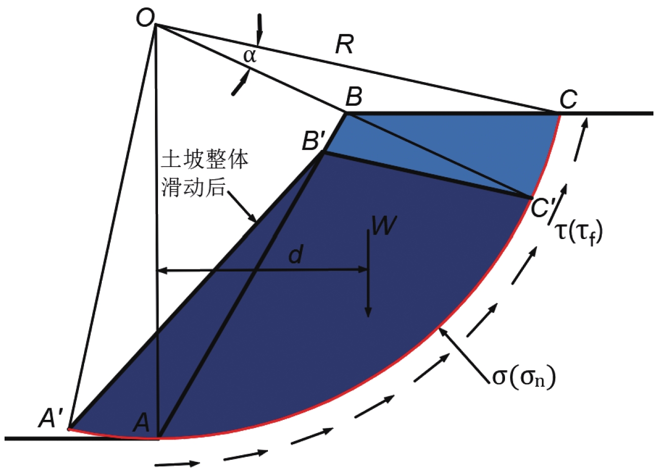
在地震诱发土坡滑坡的实际工程案例中,发现滑动面与圆弧滑动面相近,通常将其近似为圆弧面来考虑(任永强等,2011;邓东平等,2012;邢洋等,2021)。在理论分析中,各种条分法均是根据瑞典圆弧法(整体圆弧法)发展起来的,瑞典圆弧法原始的求解思想是将整个滑动土体作为一个整体,假设土体均质,滑动面为圆弧滑动面,土体呈刚性转动,在滑面上土体处于极限平衡状态,各力对圆心O的力矩平衡。假定土体单元为不变形刚体,最终建立平衡方程和圆弧滑面力矩平衡方程。当滑坡体沿圆弧滑动面发生相对滑动时,总是沿着所处位置与圆心的这一半径圆弧滑动,首先滑体发生滑动的原因是滑体的下滑力矩MS超过了抗滑力矩MR,如公式(1)、(2)所列。
$$ {M}_{S}=Wd\text{,} $$ (1) $$ {M}_{\mathrm{R}}={\int }_{0}^{L}{\tau }_{f}dl\cdot R \text{,} $$ (2) 式中:W为滑体重力,d为滑坡体重心与圆心的距离,τf为抗剪强度,l为滑动面长度,R为圆弧滑动面半径。
在上述理论和实际工程案例的基础上,本文提出的“彩虹状”位移云图失稳判据是基于地震作用下土坡滑动面为圆弧面的假定。滑坡体以O点为圆心产生整体滑移或转动,如图1所示。
当滑坡体整体转动θ角度时,滑移面上的点C移动到C′的位置,其位移为:
$$ {l}_{cc{'}}=\alpha R\text{,} $$ (3) 式中:lcc′为滑动面点的位移,α为在弧度制下所对的弧数,R为圆弧滑动面的半径。
在本研究的模拟中,考虑了不同的地震动特点,地震动可能会影响位移云图的数值大小和范围,但不会改变彩虹状位移云图的基本特征。基于上述理论推理和数值模拟结果,对结果进行分析后得出边坡失稳的特征,即当边坡整体失稳破坏时的位移云图应满足下面三个条件:
1) 滑坡体内的土体单元相对于边坡内部稳定区沿圆弧滑动面发生相对滑动。边坡内部稳定区与滑坡体在数值模拟的永久位移云图中应呈现出明显的圆弧形界限。
2) 滑坡体位移沿着顺坡向呈现出圆弧形的带状分布。分层明显,类似彩虹状,因此将其定义为彩虹状位移云图。
3) 滑坡体各层位移从坡面指向坡体内部有先增大再突变减小的现象,最大值的层带即为边坡滑动面。
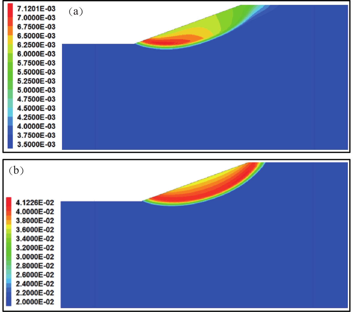
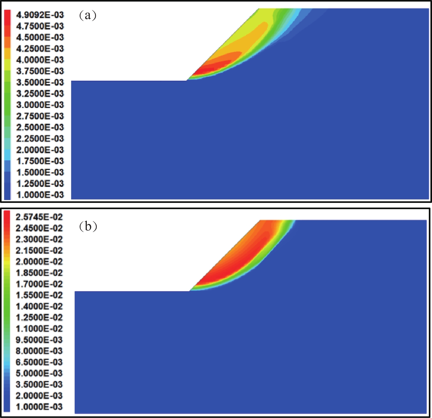
例如,图2分别为相邻两个折减系数对应的土坡地震永久位移响应云图。由图可知,此时滑坡体内部土体单元的位移值小于0.01 m,位移值较小,且同一半径圆弧形条带土体单元的位移量差异较大,并未呈现出彩虹状,表明滑坡体没有沿圆弧滑动面发生整体滑动,因此土坡处于局部破坏状态。
![]() 图 2 边坡破坏位移云图(a)局部破坏位移云图;(b)整体破坏彩虹状位移云图Figure 2. Cloud map of slope failure displacement(a) Localized damage displacement map;(b) Overall damage rainbow displacement map
图 2 边坡破坏位移云图(a)局部破坏位移云图;(b)整体破坏彩虹状位移云图Figure 2. Cloud map of slope failure displacement(a) Localized damage displacement map;(b) Overall damage rainbow displacement map将边坡继续折减到图2b,位移云图呈现出明显的圆弧形边界,满足上述三个条件(1),可认为图2b中土坡发生整体失稳破坏。
2. 算例分析
2.1 模型参数
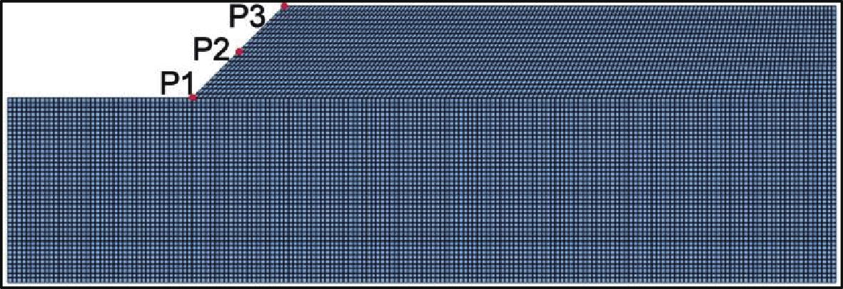
本文采用FLAC3D软件进行数值模拟,为研究地震作用下土坡失稳判据,建立边坡模型前缘长40 m,高40 m,坡顶后缘长120 m,高60 m,边坡坡高为20 m,以坡角45°的均质土坡模型为例,同时在土坡模型的坡脚、坡面中点以及坡顶处布设监测点记为P1、P2、P3,网格划分如图3所示。
本文土坡模型材料参数选取四川地区滑坡体的土体类型及相关数据,土体类型为西南地区粘土,土体物理力学参数如表1所示(曲宏略,2015;工程地质手册,2018)。
表 1 边坡土体参数Table 1. Slope Soil Parameters参数 密度
/(kg·m−3)体积模量
/MPa剪切模量
/MPa抗拉强度
/kPa粘聚力
/kPa内摩擦角
/°数值 1 900 70 37 4 32 24 在模拟地震过程中,对于均质土坡这类简单模型,局部阻尼与实际情况接近(言志信等,2011),且局部阻尼不需要估计系统的自振频率,因此更为简单有效,故本文阻尼的形式为局部阻尼。对于岩土体材料,临界阻尼比取值范围一般为2%—5% (张兆鹏,2018)。本文的研究地区及土体类型与文献(曲宏略,2015)相同,且土体参数相近,因此同样采用5%的临界阻尼比来近似表征土体在地震波传播过程中的阻尼作用,通过式(4)计算可得阻尼系数为0.157 (言志信等,2010)。
$$ \xi =\text{π} {D}_{s} $$ (4) 式中:ξ为局部阻尼系数,Ds为临界阻尼比,$\text{π} $取3.14。
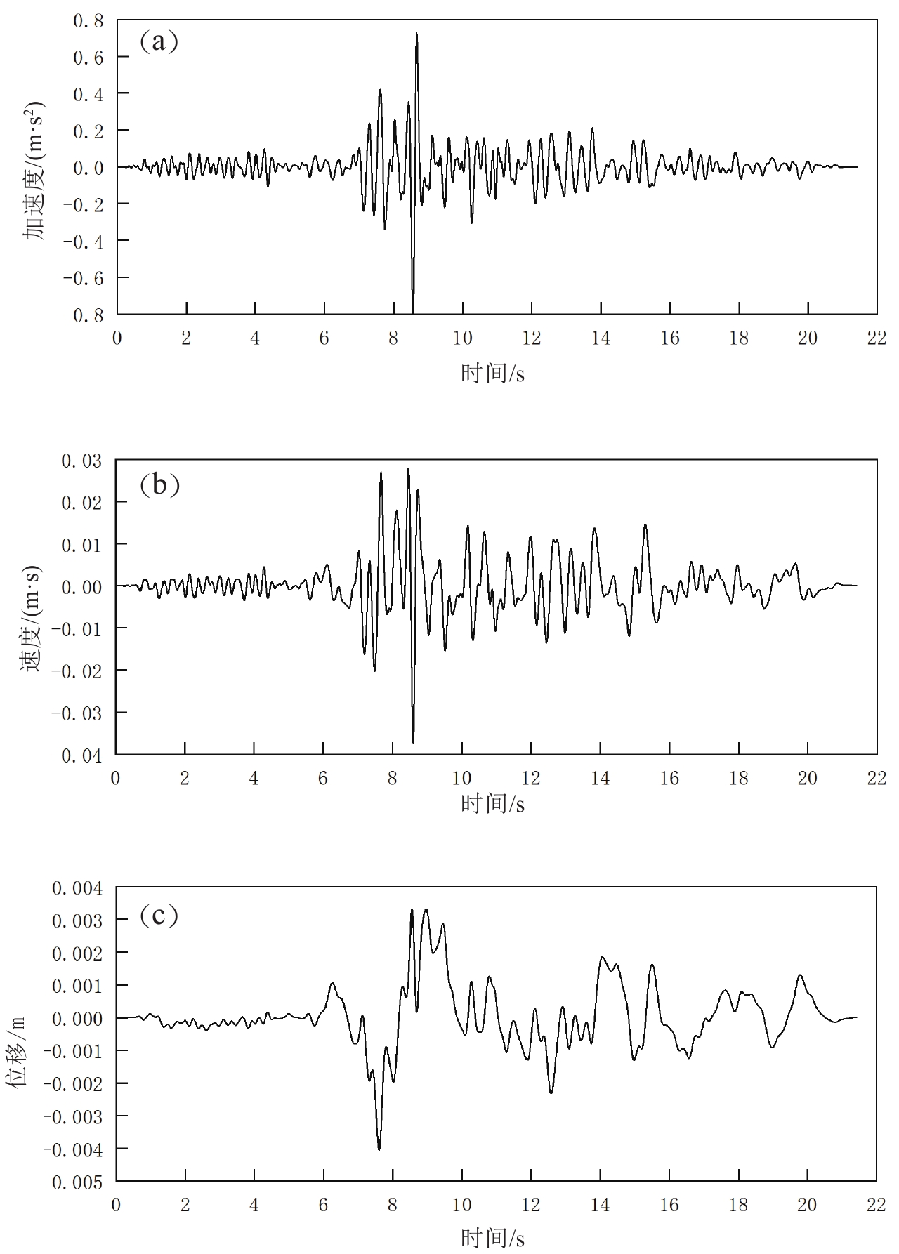
选取Trinidad地震动,时长21.41 s,峰值0.08 g,计算步数为2 141步,步长0.01 s,加速度、速度及位移时程曲线如图4所示。本文先对地震动进行了滤波处理和基线校正,然后从模型底部竖向输入水平向地震动,为了避免边界的地震波反射,模型周围施加自由场边界条件,底部采用静态边界条件,此时需要将加速度、速度时程转换成应力时程后,再施加到模型底部。在模型底部设置监测点,与输入地震动的加速度时程曲线吻合,说明地震波输入正确。
![]() 图 4 Trinidad地震动加速度、速度及位移时程曲线(a) 加速度时程曲线;(b) 速度时程曲线;(c) 位移时程曲线Figure 4. Trinidad Ground Motion Acceleration,Velocity,and Displacement Time History Curve(a) Acceleration time-course curves;(b) Velocity time-course curves;(c) Displacement time-course curves
图 4 Trinidad地震动加速度、速度及位移时程曲线(a) 加速度时程曲线;(b) 速度时程曲线;(c) 位移时程曲线Figure 4. Trinidad Ground Motion Acceleration,Velocity,and Displacement Time History Curve(a) Acceleration time-course curves;(b) Velocity time-course curves;(c) Displacement time-course curves2.2 动力有限元强度折减法
本文采用FLAC显式差分法求解微分方程,首先将计算区域离散化为若干单元。在荷载作用下,通过时间步长的有限差分形式计算节点速度和相对位移,进而求出应变和应力。通过不断迭代,求解节点的不平衡力,直至达到平衡状态(陈育民,徐鼎平,2009)。
动力力学平衡方程为:
$$ \boldsymbol{M}\left\{\ddot{u}\right\} + \boldsymbol{C}\left\{\dot{u}\right\} + \boldsymbol{K}\left\{u\right\}=\left\{F ( t ) \right\} $$ (5) 式中:M为结构的质量矩阵;C为结构的阻尼矩阵;K为结构的刚度矩阵;$ \left\{\ddot{u}\right\} $为结构的加速度列阵,$ \left\{\dot{u}\right\} $为结构的速度列阵,$ \left\{u\right\} $为结构的位移列阵,{F(t)}为结构的节点荷载列阵。
当动荷载为输入地震荷载时,基本力学运动方程可写为:
$$ \boldsymbol{M}\left\{\ddot{u}\right\} + \boldsymbol{C}\left\{\dot{u}\right\} + \boldsymbol{K}\left\{u\right\}=-\boldsymbol{M}\left\{{\ddot{u}}_{g} ( t ) \right\} $$ (6) 式中,$ {\ddot{u}}_{g} ( t ) $为输入地震加速度。
地震是一种随时间变化的复杂荷载作用,边坡岩土体在地震作用下很快会进入弹塑性状态(张江伟,2016)。边坡的稳定性安全系数,即边坡的安全储备系数(李德生,徐颖,2012)。在动力作用下边坡的研究方法中,郑颖人等(2005)提出的有限元强度折减动力分析法,在不假定滑面的情况下,既能得出边坡安全系数,又能反映岩土体的动力特性。在不断试算的基础上人为判定边坡是否失稳。在数值分析有限元计算的过程中,强度折减法指通过逐渐提高折减系数F,相应地逐渐减小土体的抗剪强度指标,直至边坡处于极限平衡的临界状态。通过失稳判据来判断此时土坡所处的状态,如果土坡失稳破坏,则减小折减系数F,反之,增大折减系数F。
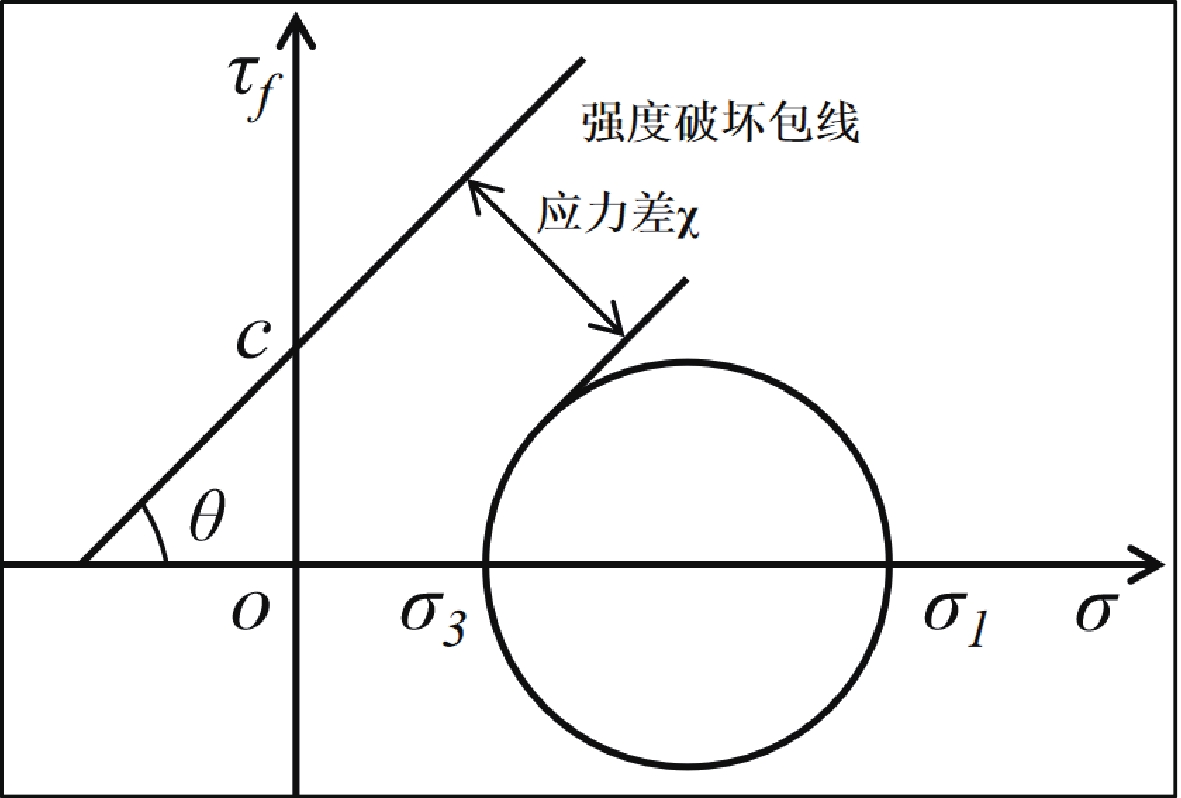
$$ {c}{{'}}=\frac{c}{F},$$ (7) $$ \mathrm{t}\mathrm{a}\mathrm{n}{\varphi }{{'}}=\frac{\mathrm{t}\mathrm{a}\mathrm{n}\varphi }{F},$$ (8) 摩尔—库伦屈服准则对边坡内部滑动面形成机理进行了较详细的说明,不论土体内部应力路径如何变化,只要岩土体试样某一斜截面上的法向正应力和切向剪应力满足摩尔—库伦强度破坏包线方程式(9)或满足主应力形式的摩尔—库伦破坏包线方程式(10),则该试样就会沿着此斜面发生剪切破坏(张坤勇等,2017)。
$$ \tau =c + \sigma \mathrm{t}\mathrm{a}\mathrm{n}\varphi \text{,} $$ (9) 式中:τ为土体的剪切强度;c为黏聚强度;σ为主应力;φ为内摩擦角。
$$ {\sigma }_{1}-{\sigma }_{3}=2c\,\, \mathrm{c}\mathrm{o}\mathrm{s}\varphi + ( {\sigma }_{1} + {\sigma }_{3} ) \mathrm{s}\mathrm{i}\mathrm{n}\varphi $$ (10) 式中:σ1为大主应力;σ3为小主应力。
图5为摩尔库伦破坏包线图。
$$ \chi =\frac{2c\,\, \mathrm{cos}\varphi + ( {\sigma }_{1} + {\sigma }_{3} ) \mathrm{sin}\varphi - ( {\sigma }_{1}-{\sigma }_{3} ) }{2} ,$$ (11) 式中:χ的实际物理意义为莫尔圆与强度包线之间的最短距离。当χ>0 时,破坏包线与莫尔圆相离,单元未破坏;当χ≤0 时,破坏包线与莫尔圆相切或相交,单元发生破坏。当潜在滑动面上所有土体单元的应力差χ≤0 时,即为边坡的极限平衡状态。
2.3 土坡地震安全系数计算
通过对模型进行多次折减计算,当折减系数F=1.25时,如图6a,最终时刻的位移云图并未出现彩虹状,而是边坡下部位移较大,上部位移量较小,处于局部失稳状态;当F=1.26时,如图6b,最终时刻的位移云图呈现出彩虹状,说明此时边坡处于整体失稳状态,则边坡的强度折减安全系数可取为F=1.25。
![]() 图 6 位移云图(a) F=1.25时位移云图;(b) F=1.26时位移云图Figure 6. Displacement Cloud Map(a) Displacement cloud at F=1.25;(b) Displacement cloud at F=1.26
图 6 位移云图(a) F=1.25时位移云图;(b) F=1.26时位移云图Figure 6. Displacement Cloud Map(a) Displacement cloud at F=1.25;(b) Displacement cloud at F=1.263. 对比其他判据结果
为了验证本文所提出方法的准确性,对比计算了其他不同判据下得到的安全系数,并对其差异性进行阐述。其中,数值软件计算不收敛这一判据对于FLAC3D来说可行性较差,在模拟计算中很难出现不收敛现象,因此在文中并未对此判据进行计算、讨论。
3.1 塑性区贯通判据
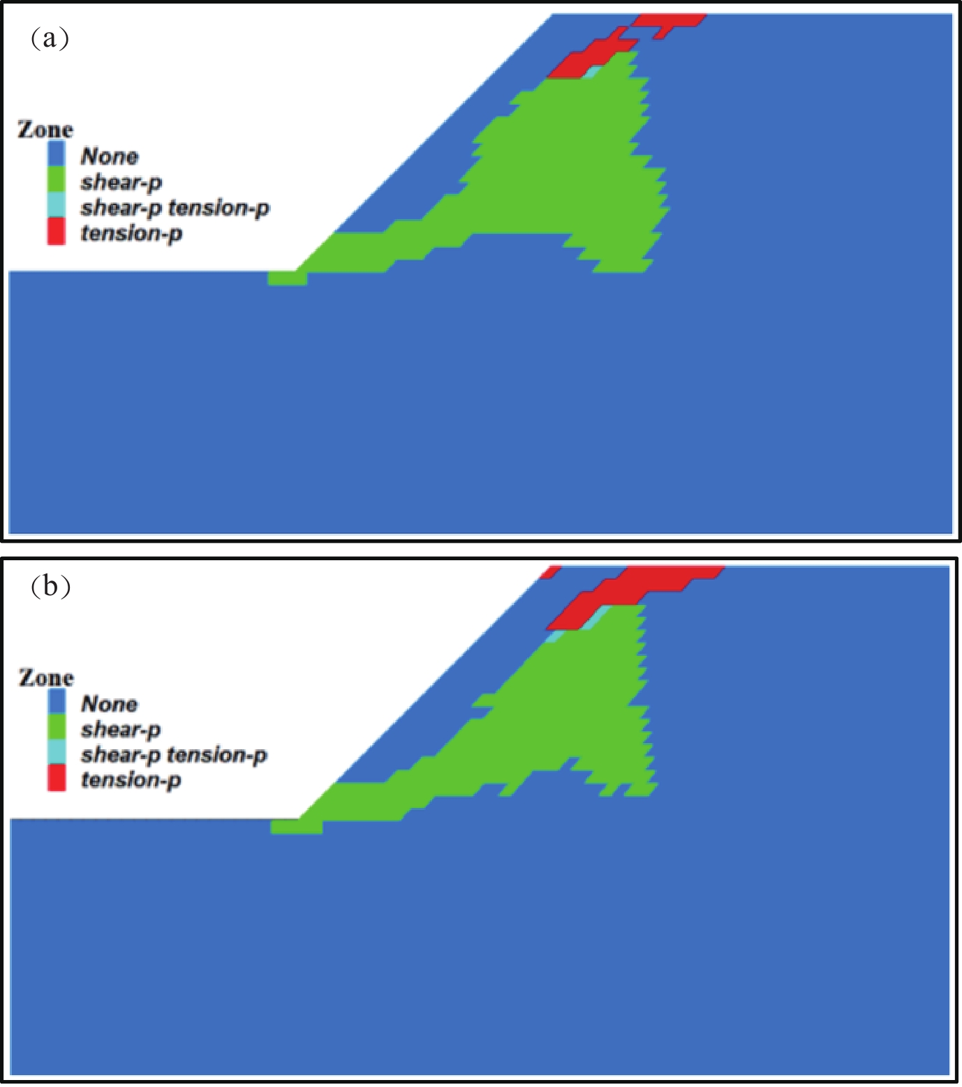
图7是边坡模型计算后的塑性区云图,土体单元由于受到剪切或者张拉作用发生剪切破坏和张拉破坏,当破坏单元由坡脚贯通至坡顶时认为边坡失稳。从图7可以看到,当F=1.23时塑性区未贯通,在F=1.24时塑性区贯通,故强度折减安全系数F=1.23。
![]() 图 7 塑性区云图(a) F=1.23时塑性区云图;(b) F=1.24时塑性区云图Figure 7. Cloud Map of Plastic Zone(a) Cloud map of the plastic zone at F=1.23;(b) Cloud map of the plastic zone at F=1.24
图 7 塑性区云图(a) F=1.23时塑性区云图;(b) F=1.24时塑性区云图Figure 7. Cloud Map of Plastic Zone(a) Cloud map of the plastic zone at F=1.23;(b) Cloud map of the plastic zone at F=1.243.2 位移突变判据
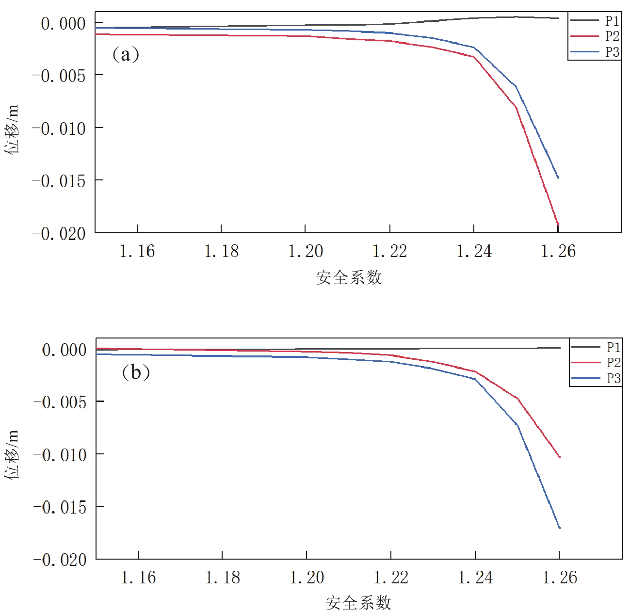
位移突变判据通常取坡脚、坡面、坡顶的特征点的最终位移与折减系数的关系曲线变化来判别边坡是否失稳,当折减系数的增大到某一特定值时,该点的最终位移突变,则认为边坡发生失稳破坏,对应的折减系数即为边坡的稳定系数。在研究特征点位移量突变这一判据时,多数采用坡顶的水平位移突变作为特征点位移判据,本文取坡脚、坡面中点以及坡顶的监测点,同时监测特征点水平向与竖直向位移。由图8可以看出,初期随着折减系数的增加,P1,P2,P3的水平向位移和竖直向位移都呈增长趋势。当折减系数增大到1.25时,P2,P3水平和竖向位移同时开始明显增大;当折减系数1.26时,位移量同时发生陡增,位移突变在1.26且继续发展。故边坡的强度折减安全系数可判定1.24—1.26之间。
![]() 图 8 强度折减系数与特征点位移量关系曲线(a) 特征点水平x方向位移与强度折减系数关系曲线;(b) 特征点水平z方向位移与强度折减系数关系曲线Figure 8. Relation Curve between Strength reduction Coefficient and Displacement of Characteristic Points(a) Characteristic point horizontal x-direction displacement versus strength reduction factor curve; (b) Characteristic point horizontal z-direction displacement versus strength reduction factor curve
图 8 强度折减系数与特征点位移量关系曲线(a) 特征点水平x方向位移与强度折减系数关系曲线;(b) 特征点水平z方向位移与强度折减系数关系曲线Figure 8. Relation Curve between Strength reduction Coefficient and Displacement of Characteristic Points(a) Characteristic point horizontal x-direction displacement versus strength reduction factor curve; (b) Characteristic point horizontal z-direction displacement versus strength reduction factor curve3.3 位移时程曲线判据
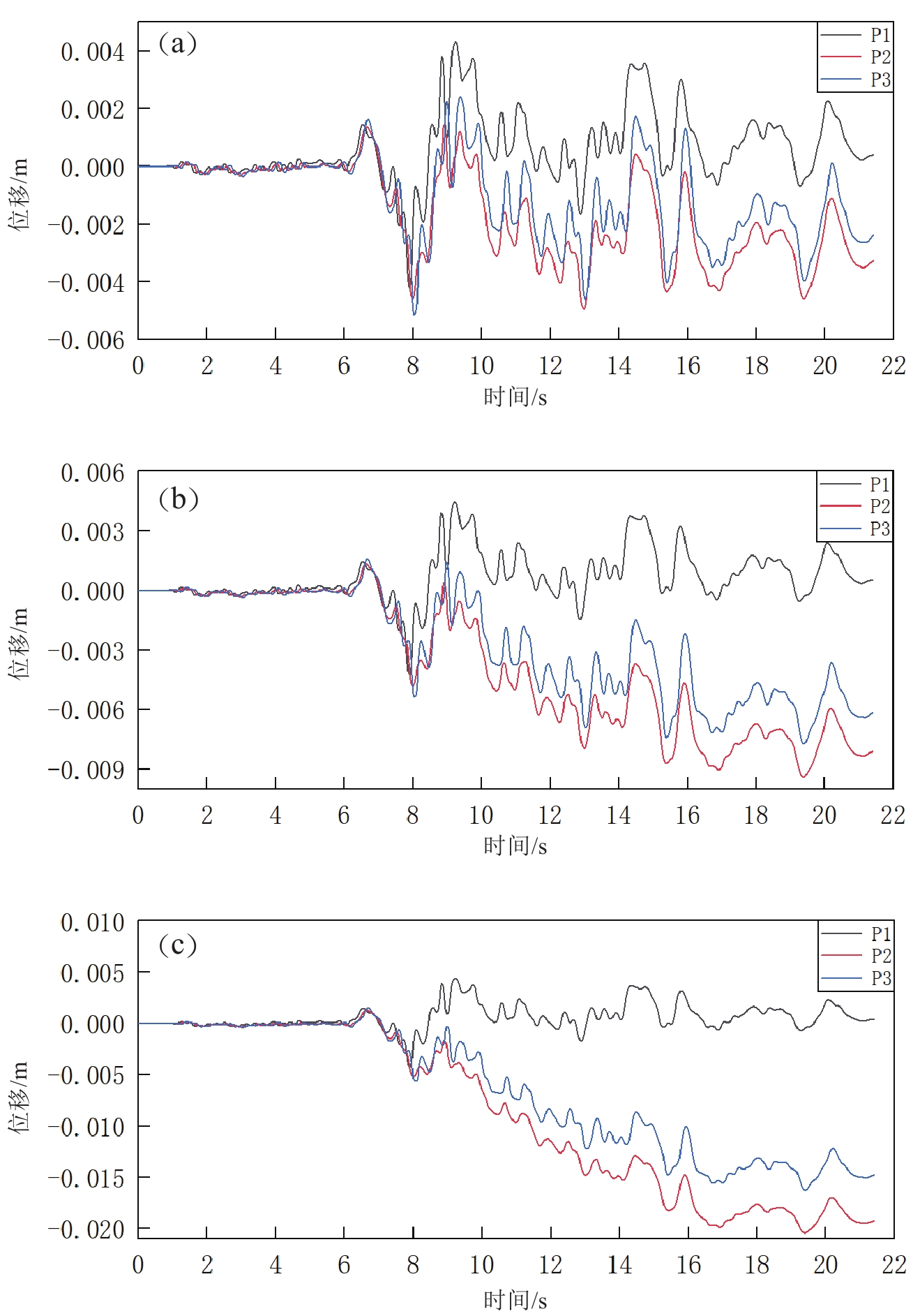
图例中1、2、3分别对应P1,P2,P3,地震作用下边坡监测点水平方向的位移曲线,如图9所示。在折减系数F=1.24时,监测点的水平向位移随着地震动的进行在0点附近规律性变化浮动,并出现一定永久位移,接着继续对土体参数折减,在折减系数F=1.25下监测点的位移时程曲线可以看出,位移曲线已经发生了一定程度的偏移,在地震过程中不能再回到0点附近,地震结束后产生了一定的永久残余位移,此时边坡应处于极限平衡或临界失稳状态。当折减系数F=1.26时,上述现象更加明显,监测点位移在原有位置上产生了较大的偏离,故认为边坡的安全系数在1. 24—1.26之间。
![]() 图 9 监测点位移曲线(a) F=1.24时监测点位移曲线;(b) F=1.25时监测点位移曲线;(c) F=1.26时监测点位移曲线Figure 9. Displacement Curve of Monitoring Points(a) Displacement curve of monitoring point at F=1.24;(b) Displacement curve of monitoring point at F=1.25; (c) Displacement curve of monitoring point at F=1.26
图 9 监测点位移曲线(a) F=1.24时监测点位移曲线;(b) F=1.25时监测点位移曲线;(c) F=1.26时监测点位移曲线Figure 9. Displacement Curve of Monitoring Points(a) Displacement curve of monitoring point at F=1.24;(b) Displacement curve of monitoring point at F=1.25; (c) Displacement curve of monitoring point at F=1.264. 讨论与结论
将四类失稳判据得到的稳定系数列于表2中。
表 2 不同判据下的安全系数Table 2. Safety Factors under Different Criteria判据
类别塑性区
贯通特征点
位移突变位移时程
曲线判据位移云图
彩虹状安全系数 1. 23 1. 24—1.26 1. 24—1.26 1. 25 通过表2中对比分析不同判据下边坡的安全系数可以发现,采用特征点位移突变、位移时程曲线和位移云图彩虹状判据得出的安全系数差距不大,说明了本文提出的判据与此前的三类判据具有一致性,也验证了其可靠性。郑颖人等提到的塑性区贯通是边坡土体破坏的必要非充分条件,本文所得结果也可以证明这点,以塑性区贯通为判据得出的安全系数相对较小,与其他判据相比误差为1.6%,出现这种差异的原因可能与网格划分的精密程度与计算精度有关。动力作用下的边坡失稳较为复杂,若采用特征点最终位移突变或者位移时程突变作为判据则需要多次折减系数计算,对于位移监测点是否陡增,更多地依赖于研究者主观上的判定,以此作为判据缺乏说服力。
在采用传统的边坡动力失稳识别方法时,往往存在主观性强、受模拟软件影响的缺陷。本文提出了“彩虹状位移云图”的概念,将边坡滑动面与位移云图相关联,实现了一种新颖且直观的边坡失稳识别方法。通过与传统判据的对比,证明了彩虹状位移云图判据求得边坡安全系数的可行性和准确性,且物理意义明确,操作简便。这使得复杂的数值模拟结果进行解析变得更为简单,提升了工程实践中的效率。
通过上述研究,可得到如下结论:
1) 采用塑性区贯通、特征点最终位移突变、位移时程曲线和彩虹状位移云图四种判据得出的安全系数差距不大,其中采用位移突变判据得到的安全系数具有主观差异性,可取范围标值。
2) 彩虹状位移云图的出现可作为地震作用下土坡整体失稳破坏的判据,物理意义明确,操作简便。同时,也可结合塑性区贯通等其他判据来确认安全系数的准确性。
3) 用特征点位移突变判据时,在选择特征点时应在坡面多选几处,坡脚处的监测点可能会因处于剪出口在其上方而导致结果不准确。
本文的研究对象为简单均质土坡,验证了本文提出的彩虹状位移判据的准确可靠性,对于岩质边坡及多级分层的非均质土坡等还有待进一步研究。
-
![]()
图 2 边坡破坏位移云图
(a)局部破坏位移云图;(b)整体破坏彩虹状位移云图
Figure 2. Cloud map of slope failure displacement
(a) Localized damage displacement map;(b) Overall damage rainbow displacement map
![]()
图 4 Trinidad地震动加速度、速度及位移时程曲线
(a) 加速度时程曲线;(b) 速度时程曲线;(c) 位移时程曲线
Figure 4. Trinidad Ground Motion Acceleration,Velocity,and Displacement Time History Curve
(a) Acceleration time-course curves;(b) Velocity time-course curves;(c) Displacement time-course curves
![]()
图 6 位移云图
(a) F=1.25时位移云图;(b) F=1.26时位移云图
Figure 6. Displacement Cloud Map
(a) Displacement cloud at F=1.25;(b) Displacement cloud at F=1.26
![]()
图 7 塑性区云图
(a) F=1.23时塑性区云图;(b) F=1.24时塑性区云图
Figure 7. Cloud Map of Plastic Zone
(a) Cloud map of the plastic zone at F=1.23;(b) Cloud map of the plastic zone at F=1.24
![]()
图 8 强度折减系数与特征点位移量关系曲线
(a) 特征点水平x方向位移与强度折减系数关系曲线;(b) 特征点水平z方向位移与强度折减系数关系曲线
Figure 8. Relation Curve between Strength reduction Coefficient and Displacement of Characteristic Points
(a) Characteristic point horizontal x-direction displacement versus strength reduction factor curve; (b) Characteristic point horizontal z-direction displacement versus strength reduction factor curve
![]()
图 9 监测点位移曲线
(a) F=1.24时监测点位移曲线;(b) F=1.25时监测点位移曲线;(c) F=1.26时监测点位移曲线
Figure 9. Displacement Curve of Monitoring Points
(a) Displacement curve of monitoring point at F=1.24;(b) Displacement curve of monitoring point at F=1.25; (c) Displacement curve of monitoring point at F=1.26
表 1 边坡土体参数
Table 1 Slope Soil Parameters
参数 密度
/(kg·m−3)体积模量
/MPa剪切模量
/MPa抗拉强度
/kPa粘聚力
/kPa内摩擦角
/°数值 1 900 70 37 4 32 24  下载: 导出CSV
表 2 不同判据下的安全系数
Table 2 Safety Factors under Different Criteria
判据
类别塑性区
贯通特征点
位移突变位移时程
曲线判据位移云图
彩虹状安全系数 1. 23 1. 24—1.26 1. 24—1.26 1. 25
下载: 导出CSV
-
崔笑,张燎军,翟亚飞,马天骁,何鎏. 2020. 基于塑性应变能理论的边坡动力稳定性研究[J]. 人民长江,51(04):180–183+190. Cui X,Zhang L J,Zhai Y F,Ma T X,He L. 2020. Study on dynamic stability of slope based on plastic strain energy theory[J]. People's Yangtze River,51(04):180–183+190 (in Chinese).
陈育民,徐鼎平. 2009. FLAC/FLAC3D基础与工程实例[M]. 北京:中国水利水电出版社. Chen Y M,Xu D P. 2009. FLAC/FLAC3D Foundation and Engineering Examples[M]. Beijing:China Water Power Press (in Chinese).
邓东平,李亮,罗伟. 2012. 地震荷载作用下土钉支护边坡稳定性拟静力分析[J]. 岩土力学,33(06):1787–1794. doi: 10.3969/j.issn.1000-7598.2012.06.029 Deng D P,Li L,Luo W. 2012. Pseudostatic analysis of stability of soil nail supported slopes under seismic loads[J]. Geotechnical Mechanics,33(06):1787–1794 (in Chinese).
工程地质手册编委会. 2018. 工程地质手册(第五版)[M]. 北京:中国建筑工业出版社. Editorial Committee of the Engineering Geology Handbook. 2018. Geological Engineering Handbook[M]. Beijing:China Architecture & Building Press (in Chinese).
华成亚,赵旭,刘子剑,曹晓立,刘洪秀. 2016. 塑性应变能判据在三维边坡稳定性分析中的应用[J]. 工业建筑,46(04):93–97+146. Hua C Y,Zhao X,Liu Z J,Cao X L,Liu H X. 2016. Application of plastic strain energy criterion in three-dimensional slope stability analysis[J]. Industrial Building,46(04):93–97+146 (in Chinese).
黄润秋. 2007. 20世纪以来中国的大型滑坡及其发生机制[J]. 岩石力学与工程学报,(3):433–454. doi: 10.3321/j.issn:1000-6915.2007.03.001 Huang R Q. 2007. Large scale landslides and their occurrence mechanisms in China since the 20th century[J]. Journal of rock mechanics and Engineering,(03):433–454 (in Chinese).
介玉新. 2023. 边坡稳定分析的相对失稳加速度方法[J]. 水力发电学报,42(2):1–11. doi: 10.11660/slfdxb.20230201 Jie Y X. 2023. The relative instability acceleration method for slope stability analysis[J]. Journal of Hydroelectric Power,42(02):1–11 (in Chinese).
李德生,徐颖. 2012. 有限元强度折减法中边坡失稳判据讨论[J]. 四川建材,38(6):121–122+125. Li D S,Xu Y. 2012. Discussion on slope instability criterion in finite element strength reduction method[J]. Sichuan Building Materials,38(06):121–122+125 (in Chinese).
刘金龙,栾茂田,赵少飞,袁凡凡,王吉利. 2005. 关于强度折减有限元方法中边坡失稳判据的讨论[J]. 岩土力学,26(8):1345–1348. doi: 10.3969/j.issn.1000-7598.2005.08.035 Liu J L,Luan M T,Zhao S F,Yuan F F,Wang J L. 2005. Discussion on slope instability criterion in Strength reduction finite element method[J]. Geotechnical Mechanics,26(8):1345–1348 (in Chinese).
吕庆,孙红月,尚岳全. 2008. 强度折减有限元法中边坡失稳判据的研究[J]. 浙江大学学报(工学版),(1):83–87. Lv Q,Sun H Y,Shang Y Q. 2008. Study on slope instability criterion in Strength reduction finite element method[J]. Journal of Zhejiang University (Engineering Edition),(01):83–87 (in Chinese).
龙绪健,黄晓燕,张春宇,周基. 2008. 有限元强度折减法中的刚度退化及边坡失稳判据[J]. 岩土工程学报,30(12):1910–1914. doi: 10.3321/j.issn:1000-4548.2008.12.024 Long X J,Huang X Y,Zhang C Y,Zhou J. 2008. Stiffness degradation and slope instability criteria in finite element strength reduction method[J]. Journal of Geotechnical Engineering,30(12):1910–1914 (in Chinese).
刘新荣,涂义亮,钟祖良,刘永权. 2016. 基于能量突变的强度折减法边坡失稳判据[J]. 中南大学学报(自然科学版),47(6):2065–2072. doi: 10.11817/j.issn.1672-7207.2016.06.034 Liu X R,Tu Y L,Zhong Z L,Liu Y Q. 2016. Slope instability criterion based on strength reduction method of energy mutation[J]. Journal of Central South University (Natural Science Edition),47(6):2065–2072 (in Chinese).
李志平,彭振斌,何忠明,唐佳. 2016. 一种基于塑性功和突变理论的边坡临界状态确定方法[J]. 中南大学学报(自然科学版),47(09):3193–3200. Li Z P,Peng Z B,He Z M,Tang J. 2016. A method for determining the critical state of slopes based on plastic work and catastrophe theory[J]. Journal of Central South University (Natural Science Edition),47(9):3193–3200 (in Chinese).
裴利剑,屈本宁,钱闪光. 2010. 有限元强度折减法边坡失稳判据的统一性[J]. 岩土力学,31(10):3337–3341. doi: 10.3969/j.issn.1000-7598.2010.10.049 Pei L J,Qu B N,Qian S G. 2010. Unification of slope instability criteria based on finite element strength reduction method[J]. Geotechnical Mechanics,31(10):3337–3341 (in Chinese).
曲宏略,胡焕国,张建经,朱大鹏. 2015. 地震动对锚索桩的响应特性研究[J]. 地震工程学报,37(2):317–323. doi: 10.3969/j.issn.1000-0844.2015.02.0317 Qu H L,Hu H G,Zhang J J,Zhu D P. 2015. Dynamic response characteristics of anchor cable piles under ground motion[J]. China Earthquake Engineering Journal,37(02):317–323 (in Chinese).
任永强,何昌荣,路永珍. 2011. 基于有限元水平地震荷载作用下土坡稳定性分析[J]. 路基工程,(6):41–44. doi: 10.3969/j.issn.1003-8825.2011.06.012 Ren Y Q,He C R,Lu Y Z. 2011. Stability analysis of soil slopes under horizontal seismic loads based on finite element method[J]. Roadbed Engineering,(06):41–44 (in Chinese).
史卜涛,张云,张巍. 2016. 边坡稳定性分析的物质点强度折减法[J]. 岩土工程学报,38(9):1678–1684. doi: 10.11779/CJGE201609015 Shi B T,Zhang Y,Zhang W. 2016. Material point strength reduction method for slope stability analysis[J]. Journal of Geotechnical Engineering,38(09):1678–1684 (in Chinese).
宋二祥. 1997. 土工结构安全系数的有限元计算[J]. 岩土工程学报,(2):4–10. Song E X. 1997. Finite Metacomputing of safety coefficient of geotechnical structure[J]. Journal of Geotechnical Engineering,(02):4–10 (in Chinese).
涂义亮,刘新荣,钟祖良,杜立兵,王鹏. 2018. 三类边坡失稳判据的统一性[J]. 岩土力学,39(1):173–180+190. Tu Y L,Liu X R,Zhong Z L,Du L B,Wang P. 2018. Uniformity of three types of slope instability criteria[J]. Rock and Soil Mechanics,39(01):173–180+1901 (in Chinese).
王飞阳,潘泓. 2016. 不同失稳判据下边坡稳定性的规律性[J]. 土木建筑与环境工程,38(6):10–16. Wang F Y,Pan H. 2016. The Regularity of Slope Stability under Different Instability Criteria[J]. Civil Architecture and Environmental Engineering,38(06):10–16 (in Chinese).
邢洋,王喜刚,刘峰,高健,田继龙. 2021. 二维边坡最危险滑动面搜索及评价研究[J]. 路基工程,(1):14–18. Xing Y,Wang X G,Liu F,Gao J,Tian J L. 2021. Research on the search and evaluation of the most dangerous sliding surface of two-dimensional slopes[J]. Roadbed Engineering,(1):14–18 (in Chinese).
言志信,张森,张学东,段建. 2010. 地震边坡失稳机理及稳定性分析[J]. 工程地质学报,18(6):844–850. doi: 10.3969/j.issn.1004-9665.2010.06.005 Yan Z X,Zhang S,Zhang X D,Duan J. 2010. Failure mechanism and stability analysis of slope under earthquake[J]. Journal of Engineering Geology,18(6):844–850 (in Chinese).
言志信,曹小红,张刘平,张海东. 2011. 地震作用下黄土边坡动力响应数值分析[J]. 岩土力学,32(S2):610–614. Yan Z X,Cao X H,Zhang L P,Zhang H D. 2011. Numerical analysis of loess slope dynamic response under earthquake[J]. Rock and Soil Mechanics,32(S2):610–614 (in Chinese).
郑宏,田斌,刘德富,冯强. 2005. 关于有限元边坡稳定性分析中安全系数的定义问题[J]. 岩石力学与工程学报,(13):2225–2230. doi: 10.3321/j.issn:1000-6915.2005.13.004 Zheng H,Tian B,Liu D F,Feng Q. 2005. On the Definition of Safety Factor in Finite Element Slope Stability Analysis[J]. Journal of rock mechanics and Engineering,(13):2225–2230 (in Chinese).
张江伟,高晓莉,李小军,王世文,王玉石. 2016. 土质边坡地震动力响应规律研究[J]. 震灾防御技术,11(4):771–780. Zhang J W,Gao X L,Li X J,Wang S W,Wang Y S. 2016. Dynamic response analysis of soil slope under seismic wave[J]. Technology for Earthquake Disaster Prevention,11(4):771–780 (in Chinese).
张坤勇,杜伟,李广山,钟思成,刘子剑. 2017. 土质边坡归一化变形量失稳判据研究[J]. 长江科学院院报,34(10):107–113. Zhang K Y,Du W,Li G S,Zhong S C,Liu Z J. 2017. Research on the criterion for normalized deformation and instability of soil slopes[J]. Journal of the Yangtze River Academy of Sciences,34(10):107–113 (in Chinese).
赵尚毅,郑颖人,时卫民,王敬林. 2002. 用有限元强度折减法求边坡稳定安全系数[J]. 岩土工程学报,(03):343–346. Zhao S Y,Zheng Y R,Shi W M,Wang J L. 2002. Calculate the safety factor of slope stability using the finite element strength reduction method[J]. Journal of Geotechnical Engineering,(3):343–346 (in Chinese).
赵尚毅,郑颖人,张玉芳. 2005. 极限分析有限元法讲座—Ⅱ有限元强度折减法中边坡失稳的判据探讨[J]. 岩土力学,(02):332–336. doi: 10.3969/j.issn.1000-7598.2005.02.035 Zhao S Y,Zheng Y R,Zhang Y F. 2005. Lecture on Finite Element Method of Limit Analysis—Ⅱ Discussion on the criterion of slope instability in finite element strength reduction method[J]. Geotechnical Mechanics,(2):332−336 (in Chinese).
张友利,彭畅,何建新. 2020. 塑性应变能判据在边坡动力稳定分析中的应用[J]. 水利科技与经济,26(12):15–18+23. doi: 10.3969/j.issn.1006-7175.2020.12.003 Zhang Y L,Peng C,He J X. 2020. Application of plastic strain energy criterion in slope dynamic stability analysis[J]. Water Conservancy Technology and Economy,26(12):15–18+23 (in Chinese).
郑颖人,赵尚毅,宋雅坤. 2005. 有限元强度折减法研究进展[J]. 后勤工程学院学报,3:1–6. Zheng Y R,Zhao S Y,Song Y K. 2005. Research progress of finite element strength reduction method[J]. Journal of the School of Logistics Engineering,3:1–6 (in Chinese).
张兆鹏. 2018. 边坡地震稳定性的数值模拟研究[D]. 中国地震局工程力学研究所. Zhang Z P. 2018. Study on Numerical Simulation of Slope Seismic Stability[D]. HeiLongJiang:Institute of Engineering Mechanics,China Earthquake Administration (in Chinese).
Zienkiewicz O C,Humpheson C,Lewis R W. 1975. Associated and non-associated visco-plasticity and plasticity in soil mechanics[J]. Geotechnique,25(4):671–689. doi: 10.1680/geot.1975.25.4.671
计量
- 文章访问数: 113
- HTML全文浏览量: 5
- PDF下载量: 44
